
Feeder — Feeder camera lamp
Feeder camera lamp (C2 and C3)
How-to guideThe OV9732 720p module clasped between its two halves, pushed into the ring on the arm, and the arm pushed up into a finished lamp. Build two.
Parts needed
Cameras
- 1×
Printed parts
- 1×
- 1×
Screws
- 2× 8mm
A an interchangeable alternative works (hover for what).
Tools needed
- Hex key, 2 mm
Build a lamp arm before you start. This page does not build the arm, the reflector or the cover: it takes a finished one and puts a camera in it. The arm's parts and its 12 screws are on that page.
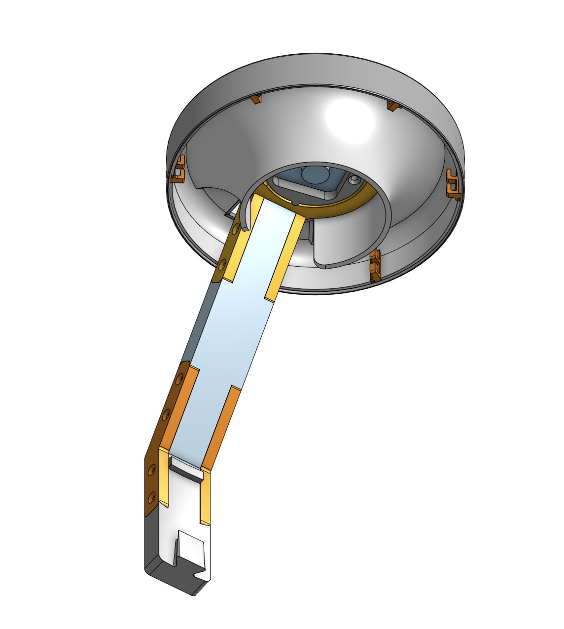
This is the lamp that hangs over C2 and C3, the two feeder channels. Build two.
It carries the OV9732 720p module. That is the only thing that differs from the classification camera lamp, which takes the IMX415 4K. The clasp, the screws and every step below are the same on both.
Fastener icons match the parts list: the silhouette is the head shape, the colour is the thread size. M3 M4 M5 M6
Step 1 Clasp the camera between the two halves
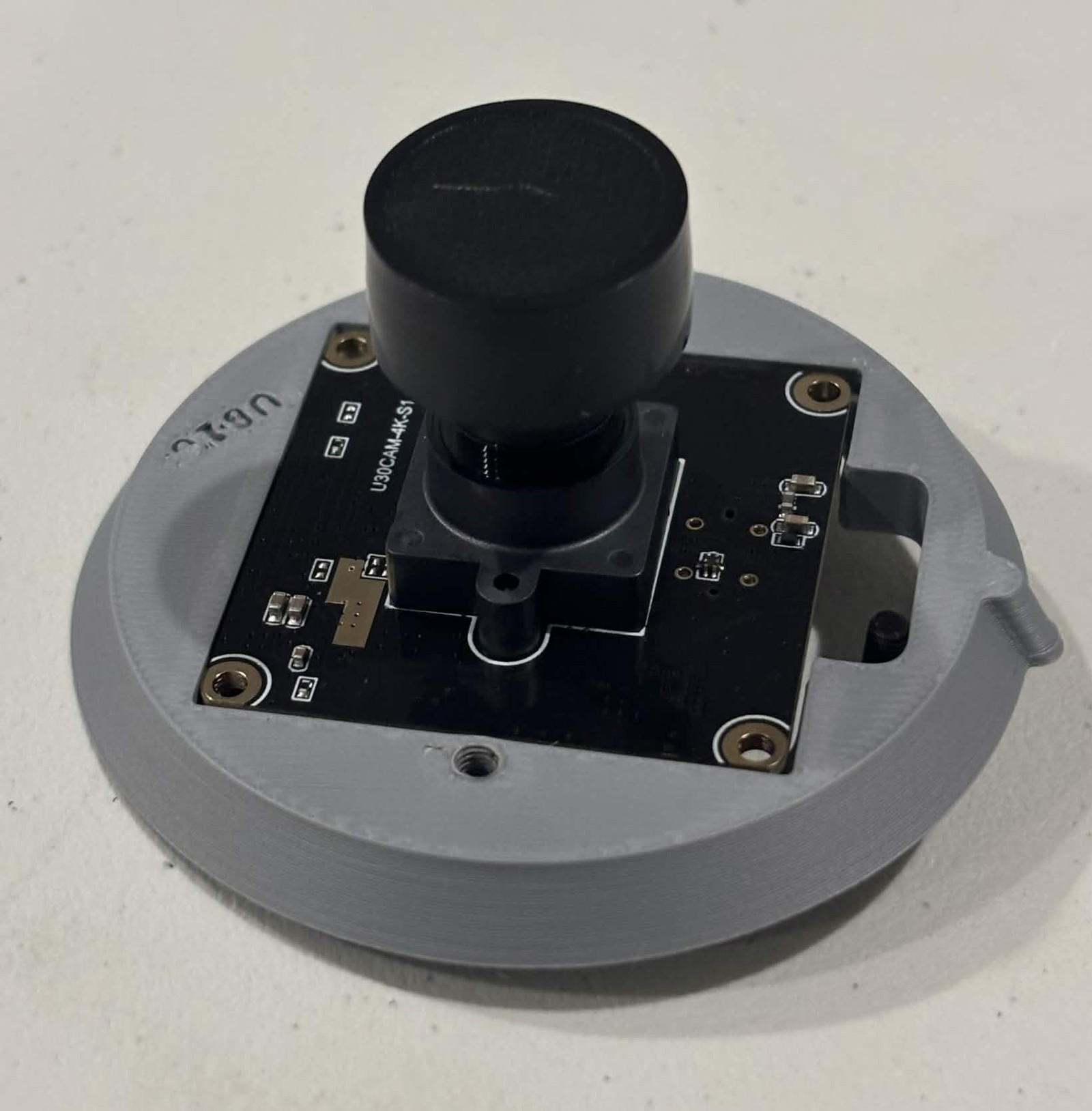
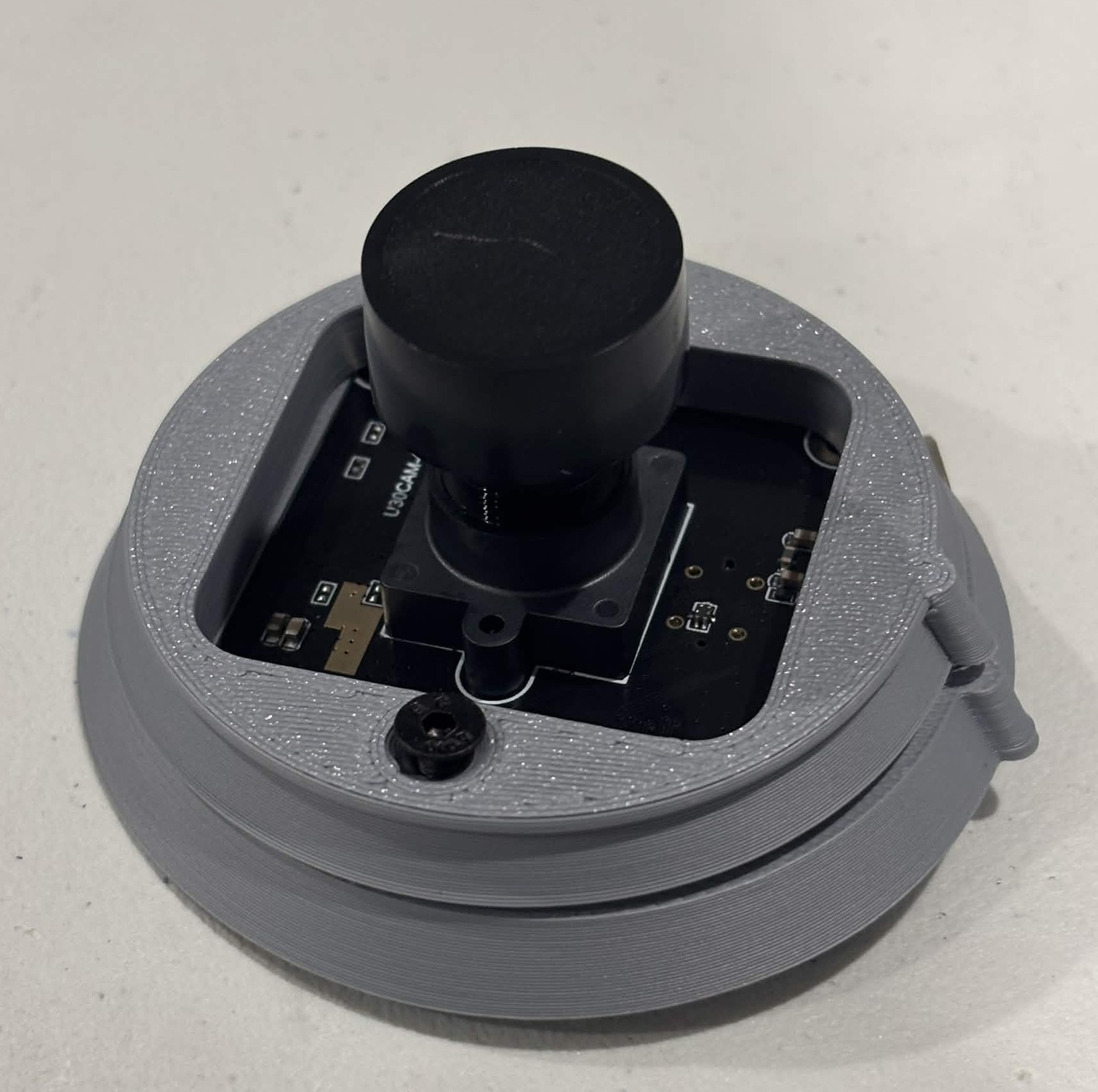
The camera board sits in the recess in the Camera clasp top. Put the Camera clasp bottom over it with the lens through the opening, and secure the two halves with 2 M3 × 8 mm countersunk screws. They go up through the bottom half into the top, one either side of the board, and seat flush in the countersinks.
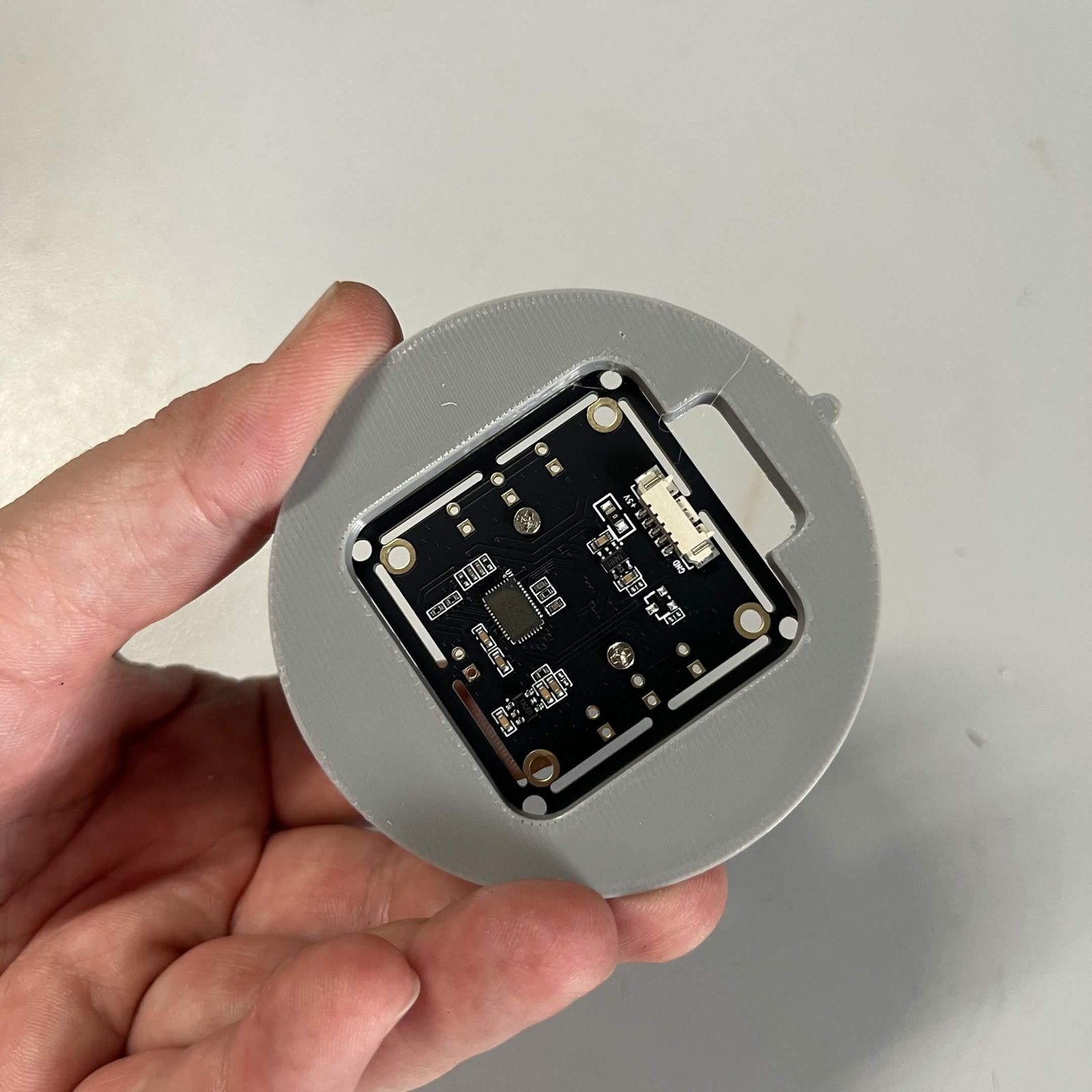
Then plug the camera's cable into the board. It ships with the camera.
Step 2 Push the clasp into the ring
Into the ring, no screws. The clasped camera pushes into the camera lamp ring on the end of the arm, with the lamp still off the arm entirely. Nothing fastens it: the only screws in this build are the two holding the clasp's own halves together.
Push until it sits firmly, not just until it meets resistance. The next step pushes the arm up inside the lamp, and a clasp that is not fully home lifts out on the way.
The clasp's two halves form a spigot that plugs into a socket in the ring. The ring has two of these sockets, and both take the clasp. The machine these steps come from uses the left-hand one on all three lamps, looking down at the lamp from above. Use the same socket on all three, keep the camera's lead running clear of the arm, and check the lens points straight down before you go on.
Which socket changes what the camera can see, not just which way up the picture arrives. If a channel's drop zone and its exit are not both in frame at first setup step 7, that is the mounting, and rotating the view in the camera settings will not fix it.
Expect it to sit loose. The lamp's cover is what traps the clasp and holds the camera in, and that happens in the next step, once the arm is up inside the lamp. Until then the camera can lift straight back out, so do not pick the arm up by it.
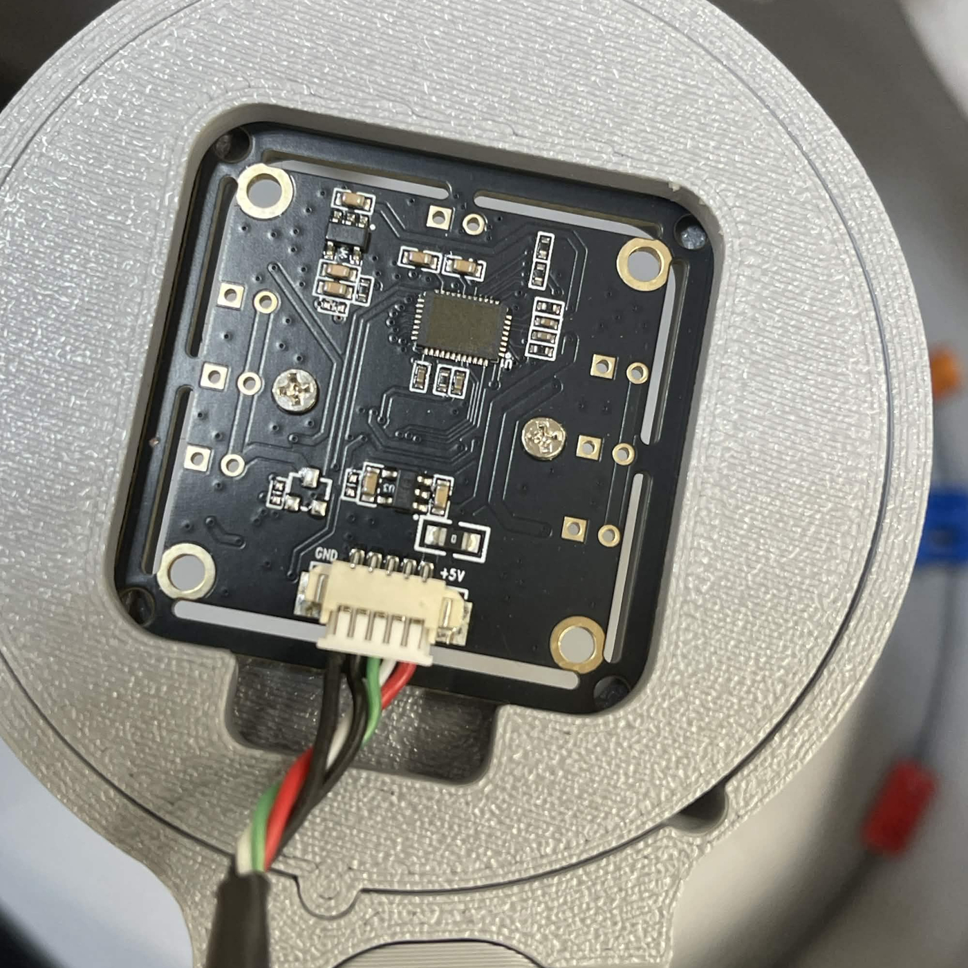
Step 3 Push the arm up into the lamp
The lamp arm page leaves you a finished lamp: reflector, LED strip and cover. It keeps its cover on for this.
- Feed the camera's lead up through the rectangular slot near the rim of the cover first, so it is clear before anything is pushed together.
- Hold the lamp and push the arm's ring up into the middle of the reflector from underneath until it seats.
That is what holds the camera in. The clasp is wider than the opening in the middle of the cover, so with the arm home the cover overlaps the clasp's rim and traps it.
It is a tight pass. The clasp is 67.76 mm across and the reflector's bore is 68.0 mm at the top, a quarter of a millimetre all round, so the clasp rubs the whole way up and can lift out of the ring as it goes. If that happens, take the arm back out, push the clasp fully home and try again.
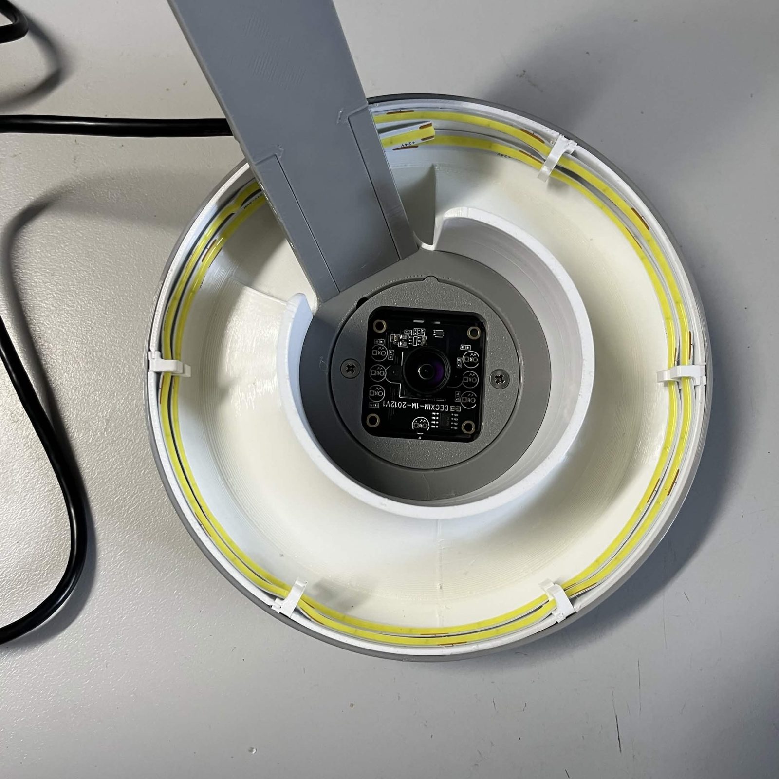
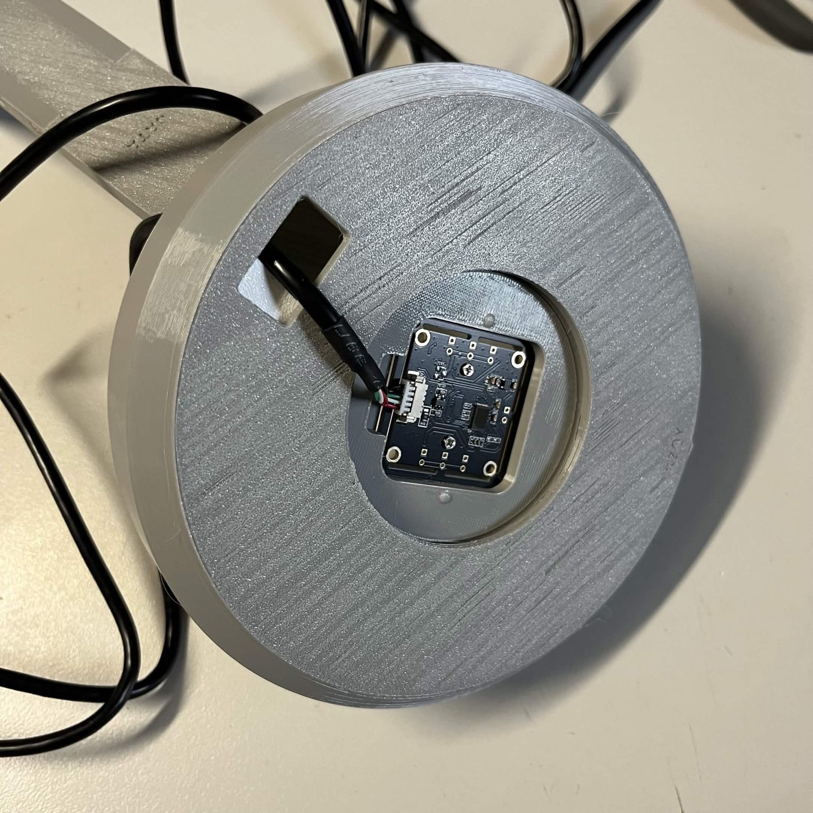
The finished result
A finished lamp: the arm, the shaded lamp and the 720p camera trapped under the cover, with its lead out through the slot. Build two. They hang onto C2 and C3 later, at step 7 of arranging C-channels, once the channels are standing.
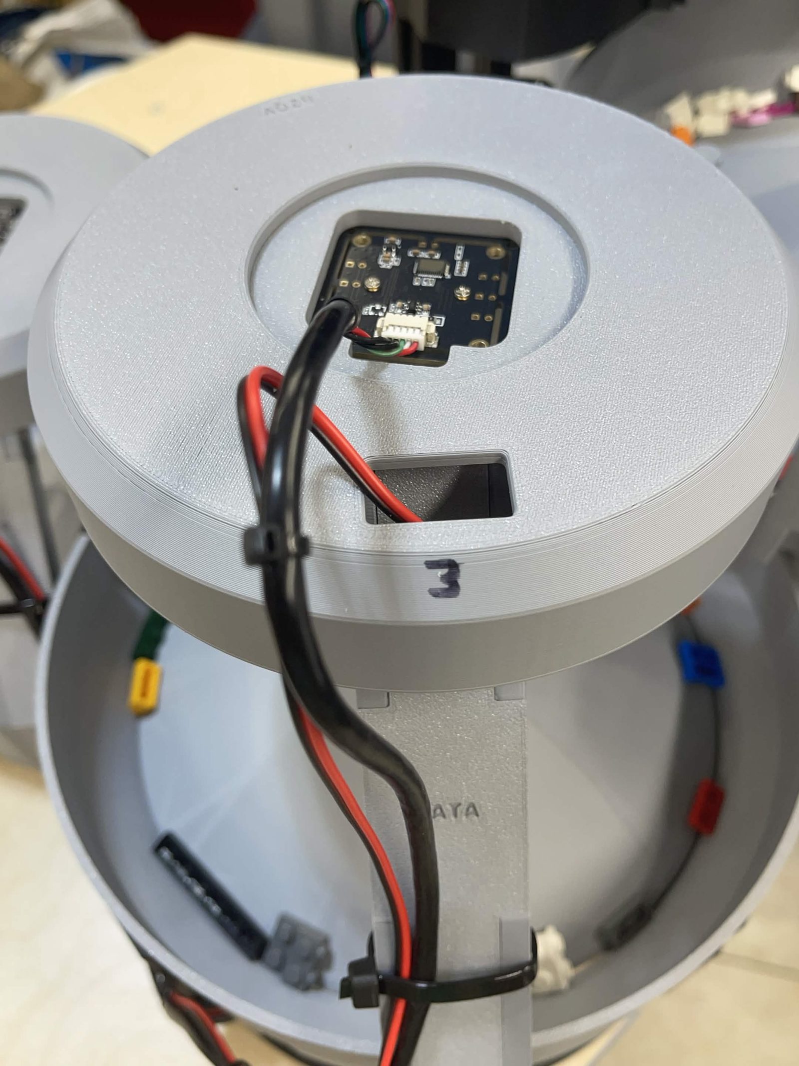
Wiring is Preparing the LED strip and its drop (L1 to L3, L1p to L3p) for the strip, and the electronics page for the camera.
Back to Camera lamps.