
Helpers — Channel stepper leads (S1 to S4)
Make the channel stepper leads (S1 to S4)
How-to guideThe four leads (S1 to S4) from the control board to the c-channel motors. Four per machine, all identical, each made by replacing the Dupont plug on the motor's own lead with a 4-pin JST connector.
Parts needed
Wire harness
- 4×Board end of S1 to S4 and CH.
- 20×Twenty-six per machine: twenty on the cables and six spares.
- 1×Optional. 1 m (39 in) per lead, 4 m (13 ft) for the four.
Tools needed
- Multimeter, to check the finished lead
- Side cutters, to cut the Dupont housing off
- Wire strippers, for 26 AWG (0.13 mm²) wire
- Crimping pliers for open-barrel contacts, with a die for 24 AWG (0.20 mm²) wire
- Optional, for the sleeving: scissors and tape, or a hot knife
These are the channel stepper leads (S1 to S4) on the harness drawings, one for each of the four c-channel motors. Four per machine, all identical. The crossover has been built on a motor's own lead by swapping the two middle contacts in its Dupont plug; this page makes the same lead with a PH housing instead of the plug.
The lead that comes in the box with the motor is not usable as it comes. Two of its four conductors are in the wrong order for this board, so the driver drives half of one coil against half of the other and the motor buzzes and barely turns. It also ends in a Dupont housing, which does fit the 2.54 mm (0.1 in) pins beside each stepper socket, so it looks right. Pull a Dupont contact sideways and its spring lifts off the pin: resistance rises, the joint heats, and it gets worse from there. Two have cooked on running machines.
Both faults are in that one housing. So the fix is to replace it: cut the plug off the motor's own lead, crimp a contact onto each of the four wires and load them into a 4-pin PHR-4 in the order below. The motor end of the lead is already right and stays as it is. Per lead: one jst-phr-4 and four jst-sph-002t contacts, so sixteen contacts for the machine. The parts list says twenty: four spares, because the first crimps on a contact this small are easy to spoil. You also need a crimp tool for open-barrel contacts. You do not need a ready-made cable or a PHR-6.
The two ends
- Board end
- JST PH housing, 4-pin (PHR-4), 2.0 mm (0.079 in) pitch, into
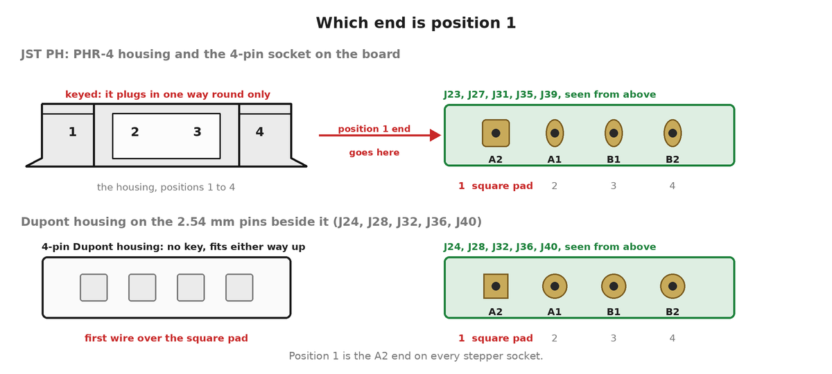
J27,J31,J35orJ39. Positions 1 to 4 areA2,A1,B1,B2. - Motor end
- The 6-pin JST PH housing the motor's lead already ends in, plugged into the socket on the motor can. Only four of the six positions carry a contact. Leave it alone.
- Wire
- The motor's own lead, four conductors of 26 AWG (0.13 mm²). The harness drawing says 1 m (39 in); see the note on length below.
The crossover
The board and the motor do not use the same positions, so this cable is not straight through. Board 1 goes to motor 1, 2 to 4, 3 to 3 and 4 to 6, which is why two wires cross in the drawing under Re-house the lead, below. Motor positions 2 and 5 stay empty.
On the motor, pin 1 is the right end of the socket when you look at the motor from the shaft end with the socket at the top edge. Reading left to right the positions are 6, empty, 4, 3, empty, 1. Positions 1 and 4 are one coil and 3 and 6 are the other, whatever colour the wires are.
Positions 1 and 2 on the board are one coil, 3 and 4 are the other. Keeping each pair together is what matters. Swapping the two wires inside a coil only reverses which way the motor turns, and the direction is set in the software.
Re-house the lead the motor came with
Check the wire diagram that came with your motor before you cut anything. StepperOnline supplies a small wire diagram with the motor that names the wire in every position of the 6-pin housing, with its colour and its coil (A+, A-, B+, B-). Lay the motor's own drawing next to the figure below: positions 1 and 4 must be the same coil, and positions 3 and 6 the other. If your drawing differs, follow it.
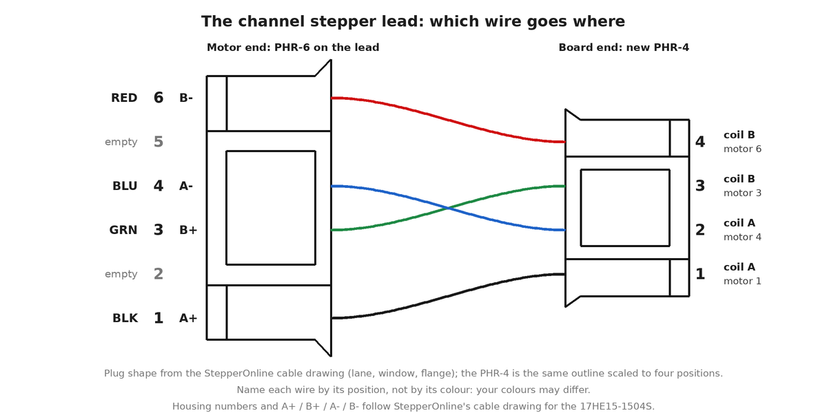
Position 1 is the end that lands on pin 1. Both housings are keyed and only plug in one way round, so the end that goes over pin 1 of the socket is position 1 and the positions count away from it. On the motor it is the end described under The crossover, above, and on the board it is the square pad. The wire colours on the drawing are an example: your wires may be other colours, and the drawing still works because each wire is named by the motor-end position it sits in.
- Look at the back of the 6-pin housing at the motor end while it is still plugged into the motor, with the shaft towards you: position 1 is the right-hand end and the positions count 1 to 6 from right to left. Four wires sit in positions 1, 3, 4 and 6, and 2 and 5 are empty. Write down which colour is in which position, or tag each wire with a bit of tape marked with its position if two look alike.
- Cut the Dupont housing off, close to it, so the cable keeps its length.
- Optional: if you will sleeve the lead, slide a 1 m (39 in) length of braided sleeving over the four wires from the cut end now, before you load the 4-pin housing. The 6-pin housing on the other end is too big for it to go over. Leave it bunched up on the cable for now; Sleeving (optional) says how to cut and finish it.
- Strip about 2 mm (0.08 in) off each conductor and crimp a contact onto it, in the die of the open-barrel crimping pliers marked for 24 AWG (0.20 mm²) wire. The motor's own wire is 26 AWG (0.13 mm²), which a PH contact takes (24 to 28 AWG), and the 24 AWG die is the one to use. Pull on each wire to check it holds. How to crimp a contact, with a picture, is at [Crimping connectors](/hardware/helpers/crimping/). Practise on a scrap first, the contacts are small and easy to spoil.
- Load the
PHR-4from the back, counting from the end that goes over the square pad of the board socket (offer the empty housing to the socket to see which end that is): the wire from motor position 1 into position 1, the wire from motor position 4 into 2, the wire from motor position 3 into 3 and the wire from motor position 6 into 4. Push each contact in until it clicks. - Pull gently on each wire, then meter across
PHR-4positions 1 and 2 and across 3 and 4 with the motor plugged in. Both read a couple of ohms, 2.3 Ω on the motor in the parts list, and across the two pairs is open circuit. If either pair reads open, two contacts are in the wrong places.
Sleeving (optional)
You can skip this and the lead works the same. The sleeving is on the parts list as optional. It keeps the four wires of each lead together as one tidy cable, and it protects them where the lead runs along the frame and past the moving parts. The parts list sells a braided sleeving for it.
Where: over the four wires of each lead, from just behind the 6-pin motor housing to just short of where the wires fan out into the PHR-4. One metre (39 in) per lead, four metres (13 ft) for the machine.
How:
- Push the braid together lengthwise to open it: it widens as it shortens. Feed the four wires into it together, so none of them is left outside.
- Cut it to length with a hot knife or a soldering iron with a blade tip, so the cut melts shut. Plain scissors leave the braid fraying. With no hot tool, wrap a turn of tape around the braid where you will cut, cut through the middle of the tape with scissors, and leave the tape on.
- Stop the sleeving 5 to 10 mm (0.2 to 0.4 in) short of the PHR-4 and short of the 6-pin housing, so the crimped contacts and the housing can flex and the sleeving never crowds into a housing.
- Hold each end with a small piece of heat shrink or a turn of tape, so that the braid cannot creep back along the wires.
Leave the sleeving loose enough to bend. The anchor under How long, below, goes on over the sleeving: pull the strap tight enough to hold, but not so tight that it crushes the braid.
How long
The length is not measured. The harness drawing says 1 m (39 in), which is also what the motors ship with and the length you keep. It was set while the c-channel positions were still moving, so check the run on your own frame before you cut the plug off.
Whatever the length, anchor the cable above the connector. Strap it to the frame a short way back from the plug with a hook-and-loop strap rather than a zip tie (why), and leave a service loop, so that nothing hanging off the cable can lever the housing sideways.
The finished result
Four leads (S1 to S4), each with a 4-pin PHR-4 at the board end and a 6-pin PHR-6 at the motor end with two of its six positions empty.
Where it goes
Onto the four channel stepper sockets at connecting the components, step 2, which is also where the socket decides which motor the software drives.
Reference
The vendor drawing for this cable (S1 to S4), its bill of materials and its downloads are on the WireViz
drawings page. It shows the same lead in the form a cable supplier quotes from.