
Feeder — Channel core
Channel core
How-to guideThe drive under every C-channel, from the stator down to the stepper.
Parts needed
Printed parts
- 1×
- 1×
- 1×
- 1×
Motors
- 1×
Bearings
- 1×
Screws
- 5× 16mm
- 2× 12mm
- 1× 8mm
Tools needed
- Hex key, 2 mm
The channel core is a C-channel with no rotor in it: the stator, the NEMA bracket under it, and the gear train the stepper drives.
The parts list above is one core's worth. Build four, three for the feeder and one for the classification channel. All four are the same. Which rotor goes in, and what hangs off it, is on the four channel pages.
Fastener icons match the parts list: the silhouette is the head shape, the colour is the thread size. M3 M4 M5 M6
- Colours. The stator is ash grey. The idler and input gears follow the feeder colour, charcoal by default. The NEMA bracket is charcoal on C1 and ash grey on the other three.
Step 1 Preparation
Idler gear (24T): press the 608-2RS bearing into it. No screw, no glue, no heat.
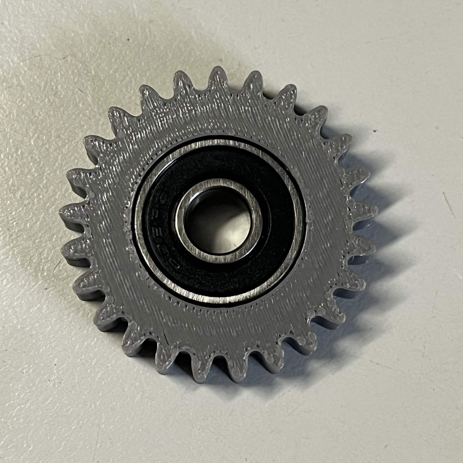
Step 2 Fit the input gear to the motor shaft
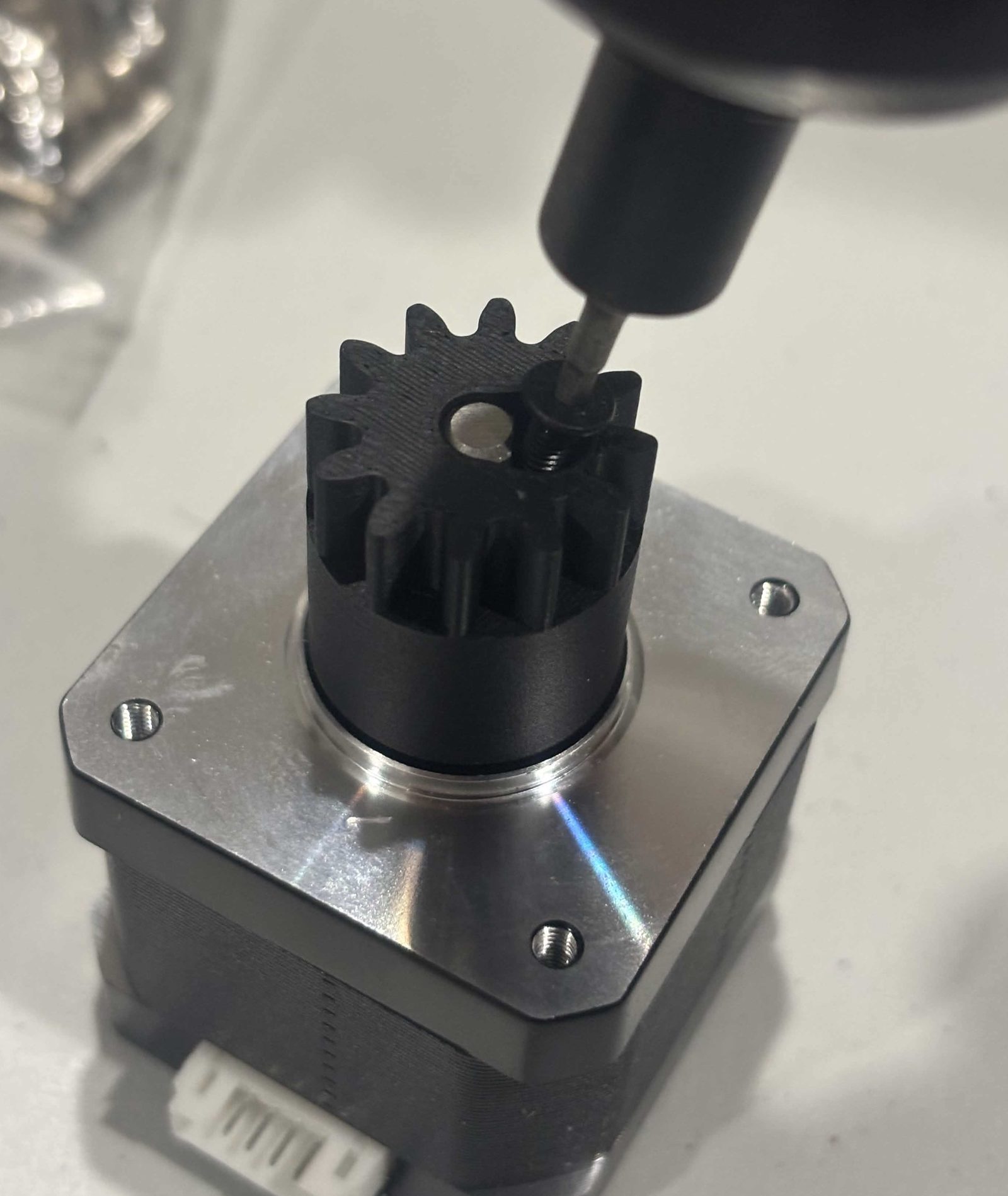
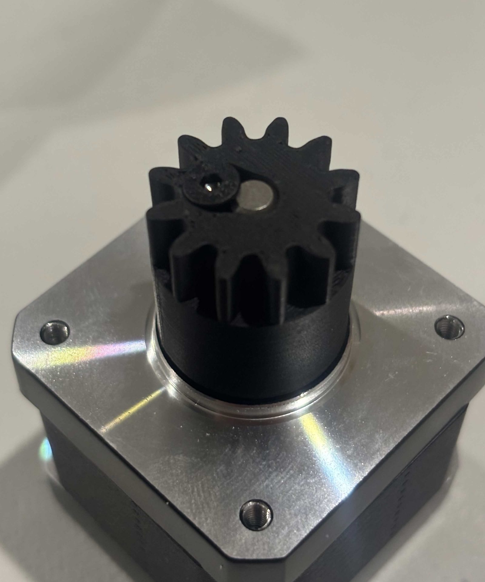
One M3 × 8 mm countersunk screw clamps the Input gear (12T, screw) to the motor shaft. It goes in beside the bore, parallel to the shaft, not into the side of the gear.
- Turn the gear until the screw hole lines up with the flat on the motor shaft.
- Push the gear all the way onto the shaft.
- Tighten the screw down onto the flat. Its head drops into the counterbore in the toothed face.
Stop when the head is seated and the gear does not turn on the shaft.
Step 3 Fit the idler gear and the stepper to the NEMA bracket
- Drop the Idler gear (24T) onto its post on the bracket, bearing facing up.
- Lower the NEMA 17 onto the bracket. The input gear meshes with the idler as it goes down.
- Drive 3 M3 × 16 mm countersunk screws through the bracket into the motor.
Three screws, not four: one corner of the motor face is left empty.
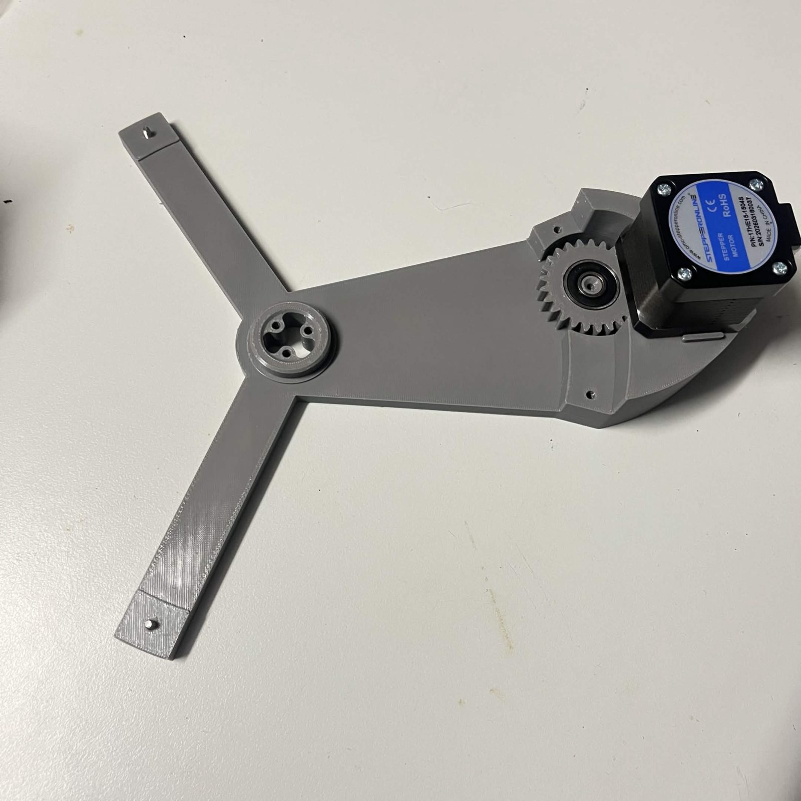
Step 4 Mount the bracket under the stator
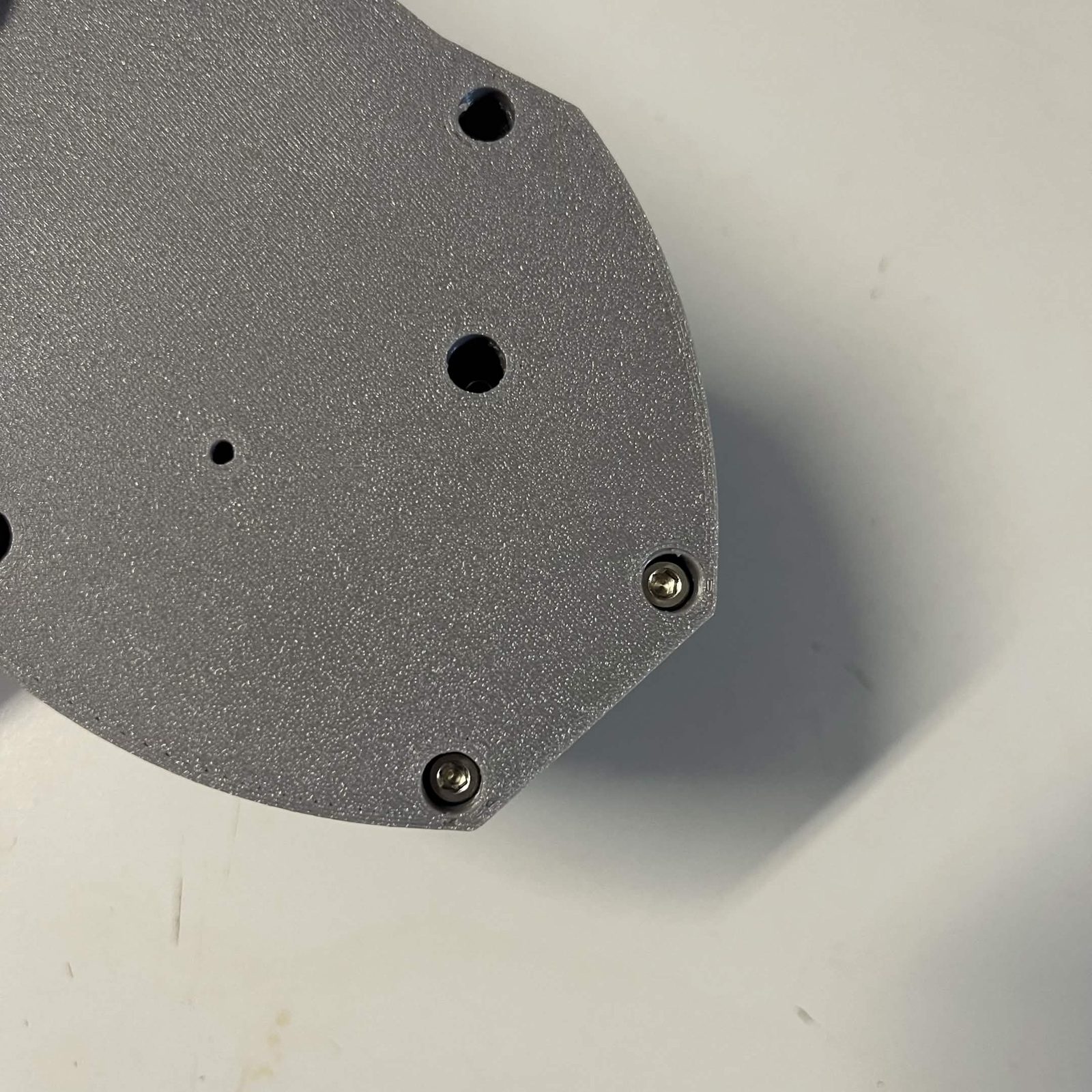
The bracket goes on the underside of the stator, held by four screws in two lengths.
- Two M3 × 12 mm countersunk at the tips of the two narrow arms.
- Two M3 × 16 mm countersunk through the wide plate the stepper sits on. The bracket is thicker there, and a 12 mm barely bites.
Turn the gear train by hand before you go on. It should run without a tight spot.
The finished result
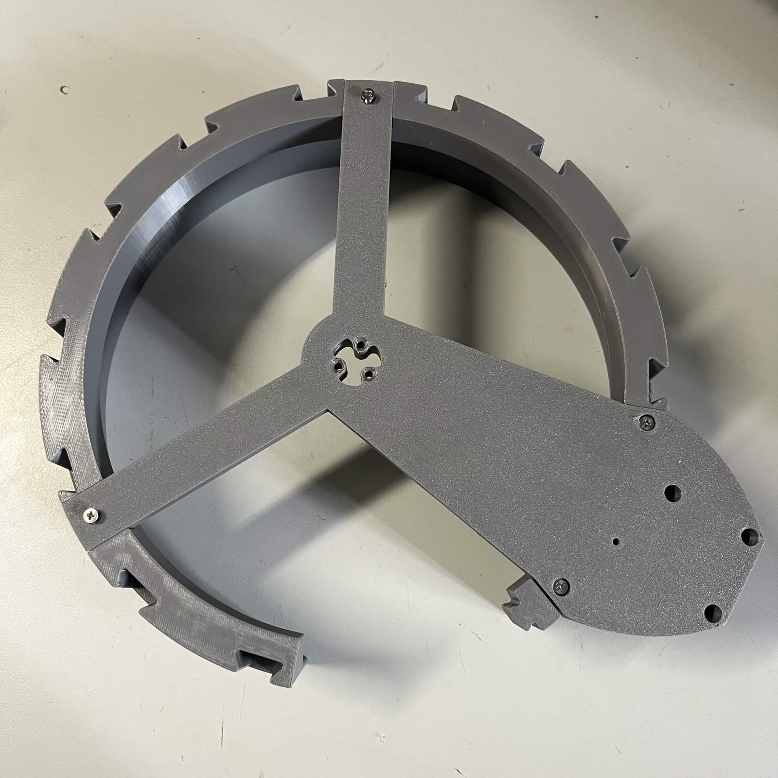
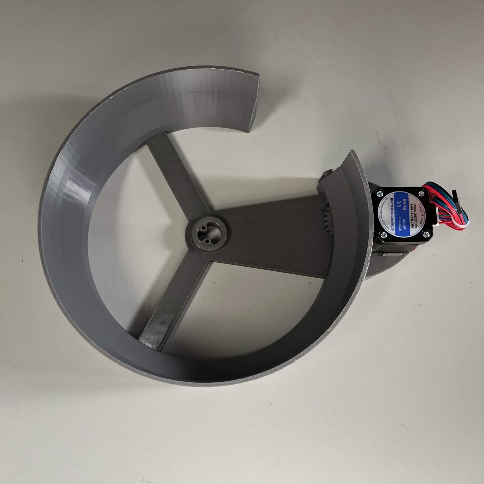
A stator with the bracket, gear train and stepper under it, and an empty hub in the middle waiting for a rotor. Build four.
Next steps
Finish each core as the channel it is going to be:
- Bulk channel (C1), the faceted rotor and the Bulk cap.
- Feeder channels (C2 and C3), the faceted rotor, an output guide and a camera lamp.
- Classification channel (C4), the finned rotor, its cap and a camera lamp with the 4K module.