
Helpers — Orange Pi 24 V lead (W3)
Make the Orange Pi's 24 V lead (W3)
How-to guideA barrel plug onto the buck converter's own input wires, so the Pi runs off the same 24 V supply as everything else. One per machine.
Parts needed
Wire harness
- 1×
- 1×Three per machine, one each on W1, W2 and W3.
- 1×0.76 m a machine: the limit switch cable and, if the converter's wires are short, the Orange Pi lead.
- 4×Two per lamp, one for each wire of the barrel socket, and two on each of the control board's and the Orange Pi's 24 V leads. Six more are spares.
- 1×Optional. About 100 mm (4 in) over the converter's two input wires.
A an interchangeable alternative works (hover for what).
Tools needed
- A ruler or tape measure, to measure the converter's input wires
- Side cutters, only if you have to extend the wires
- Wire strippers, for 22 AWG (0.33 mm²) wire, only for a moulded plug or extended wires
- Insulated-terminal crimping pliers with a die for 22 to 16 AWG (0.33 to 1.3 mm²) wire, for the butt connectors on a moulded plug or extended wires
- A small screwdriver, only for a screw-terminal plug
- Multimeter, to find the tip and to check the finished lead
- Only if you solder the joints instead of crimping them: a soldering iron, solder and adhesive-lined heat shrink (see Getting started)
- Optional, for the sleeving: scissors and tape, or a hot knife
This is the Orange Pi's 24 V lead (W3) on the harness drawings. It runs from one of the three jacks on the PSU box to the buck converter, and the converter's own USB-C lead is the rest of the run to the Pi. One per machine.
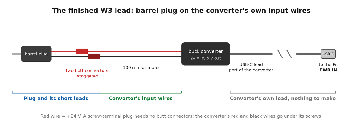
This is the shortest of the three 24 V leads and the only one with no connector at its far end. The converter arrives with bare input wires, so the whole job is putting a barrel plug on them, and usually without adding any wire. The lead to the board (W1) is the other one you make; the one to the USB hub (W2) is just a barrel plug screwed into the hub's own power terminal, with no page.
The two ends
- PSU end
- Male DC barrel plug, 5.5 mm (0.217 in) outside and 2.1 mm (0.083 in) inside, centre-positive. A 2.5 mm (0.098 in) plug looks identical and does not mate.
- Converter end
- No connector. The converter's own two input wires, red positive and black negative, printed on its case.
- Wire
- None, usually. The harness gives this lead as 150 mm (6 in) of 22 AWG (0.33 mm²), and the converter arrives with most of that already: the one measured is about 120 mm (4.7 in). Under 100 mm (4 in) is where you add wire, and that is the only reason this lead ever gets spliced.
The converter takes 8 to 32 V in and gives 5 V out at up to 5 A. It is potted, so there is nothing to open and nothing to adjust, and its output is a captive USB-C lead.
Build it
- Measure the converter's own input wires with a ruler, from the case to the cut end. 100 mm (4 in) or more and nothing needs extending: they go straight to the plug. Shorter than 100 mm (4 in), do step 2 first; otherwise skip it.
- Only if they are short. Cut a red and black pair of 22 AWG (0.33 mm²) wire with side cutters, long enough to make the lead up to about 150 mm (6 in). Join each wire of it to the converter wire of the same colour with a butt connector, red to red and black to black. How is under Joining two wires with a butt connector, below.
- Work out which terminal of the plug is the tip. A screw-terminal plug is usually marked
+and-; a moulded one is two wires. Either way, set the multimeter to continuity and hold one probe on the centre pin inside the plug: the terminal or wire that beeps is +24 V. This is the step where you find out rather than assume. On a moulded plug, put a turn of tape on the tip wire so you can tell it from the other. - Optional: if you will sleeve the lead, slide a 100 mm (4 in) length of braided sleeving over the converter's two input wires from the free end now, before you fit the plug. A finished plug may not go through it, so it goes on first. Leave it bunched up near the converter for now; Sleeving (optional) says how to cut and finish it.
- Fit the plug, the converter's red wire to the tip and its black wire to the sleeve. On a screw-terminal plug, get the bare strands fully under the screws, tighten firmly and pull on each wire. On a moulded plug, join the converter's red wire to the plug's tip wire and the converter's black wire to the plug's other wire, one butt connector each, as in step 2. Stagger the two connectors by a few millimetres along the lead so they cannot touch.
- Check the output, as under Check the lead, below.
Joining two wires with a butt connector
Used in step 2 and, on a moulded plug, in step 5. A butt connector is a vinyl-insulated barrel that takes one wire in each end, rated for 22 to 16 AWG (0.33 to 1.3 mm²) wire. Make one joint at a time so the two never touch. The list has four, two more than the lead can use, for a first crimp that goes wrong. More on crimping is at Crimping connectors.
The listing for the converter does not give the gauge of its input wires. Before you crimp, strip one wire and push it into the connector: the strands should fill the barrel. If they sit loose with room to spare, the wire is too thin for this connector, so solder it and cover the joint with heat shrink instead.
- Strip 7 mm (0.28 in) off each of the two wires, and twist the strands of each tight.
- Push one wire into each end of the butt connector, until the insulation of each wire meets the end of the barrel.
- Close each end of the barrel in the die of the insulated-terminal crimping pliers marked for 22 to 16 AWG (0.33 to 1.3 mm²), so each wire is crimped separately. Squeeze until the tool releases. Pull on each wire to check it holds.
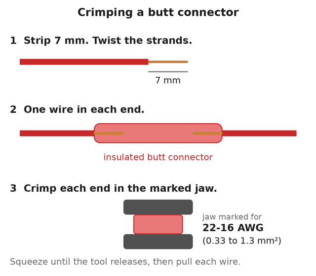
Choose the die by the size marked on it, not by its colour. To solder instead of crimping, solder the two wires together and cover each joint with a 25 mm (1 in) piece of 3 mm (0.12 in) adhesive-lined heat shrink (see Getting started).
Use insulated-terminal crimping pliers. A crimp tool for open-barrel contacts has the wrong die and will not close a butt connector properly.
Check the lead
Check the output before it goes anywhere near the Pi. A converter wired backwards can pass the input straight through, and 24 V into the Pi ends the Pi.
- With the lead not plugged in anywhere, set the multimeter to continuity. The plug's centre pin must beep to the converter's red input wire and the plug's metal sleeve to its black input wire. The pin and the sleeve must not beep to each other. If any of these is wrong, a joint is on the wrong wire: fix it before going on.
- Plug the finished lead into a PSU box jack, with nothing on the USB-C end.
- Set the multimeter to DC volts and meter the USB-C plug. Each row of its contacts has 12 in a line: the contact at the very end of a row is ground and the fourth contact in from either end of the same row is +5 V. Touch the black probe to the end contact and the red probe to the fourth one. It reads about 5 V.
- If it reads 0 V, or anything near 24 V, unplug the lead from the jack at once and check which wire went to the tip.
Sleeving (optional)
You can skip this and the lead works the same. The sleeving is on the parts list as optional. It keeps the wires together as one tidy cable and protects them where the lead runs along the frame, and it is another way of securing the cables.
Where: over the converter's two input wires, from just clear of the converter's case to just short of the plug. About 100 mm (4 in), which is a short run, so this one does little beyond keeping the two wires together.
How:
- Push the braid together lengthwise to open it: it widens as it shortens. Feed all the wires into it together, so none of them is left outside.
- Cut it to length with a hot knife or a soldering iron with a blade tip, so the cut melts shut. Plain scissors leave the braid fraying. With no hot tool, wrap a turn of tape around the braid where you will cut, cut through the middle of the tape with scissors, and leave the tape on.
- Stop the sleeving 5 to 10 mm (0.2 to 0.4 in) short of the plug, and short of its butt connectors on a moulded plug, so the sleeving never crowds into the joints.
- Hold each end with a small piece of heat shrink or a turn of tape, so that the braid cannot creep back along the wires.
The finished result
The converter with a barrel plug on its input wires and its USB-C lead free. One per machine (W3), and that is the whole lead.
The plug goes into any of the three jacks on the PSU box, all three the same 24 V. Where the USB-C end goes is at connecting the components, step 6.
Reference
The drawing for this lead (W3), its bill of materials and its downloads are on the WireViz drawings page.