
Helpers — PSU output pigtail (PJ1 to PJ3)
Make your own PSU output pigtail (PJ1 to PJ3)
How-to guideBuild one of the three DC output pigtails (PJ1 to PJ3) for the PSU box, a panel-mount barrel jack with a crimp fork terminal on each of its two leads.
Parts needed
Wire harness
- 3×Three per machine, with the 18 AWG (0.82 mm²) leads already attached. The fork terminals go on afterwards.
- 8×Eight per machine: six on the pigtails and two spares. The 8 mm width limit is the one that bites.
Tools needed
- Wire strippers, for 18 AWG (0.82 mm²) wire
- Ratcheting crimping pliers with a die for 22 to 16 AWG (0.33 to 1.3 mm²) insulated terminals, for the fork terminals
- Multimeter
The PSU box has three DC outputs. Each one is a short pigtail (PJ1 to PJ3): a panel-mount barrel jack at one end, a crimp fork terminal on each of its two leads at the other. Build three, one for each 24 V load: the basically board, the USB hub and the Orange Pi buck. All three are the same, so it does not matter which one goes to which load. Three need six fork terminals; the list has eight, two for a crimp that goes wrong. More on crimping is at Crimping connectors.
Buy the jacks with their leads already attached. This page assumes that. It crimps the terminals onto leads the jack already has. A bare jack means soldering the leads on, which this page does not cover.
The jack's 2.1 mm (0.083 in) pin is the thing to check when you buy: a 2.5 mm (0.098 in) one looks identical and does not mate.
Build it
- Start from a panel-mount jack with its leads already attached.
- Work out which lead is the tip (+24 V) and which is the sleeve (ground). The jack is centre-positive, so red is the tip and black is the sleeve. If the leads are not red and black, set a multimeter to continuity and hold one probe on the centre pin inside the jack: the lead that beeps is the tip.
- Crimp a fork terminal onto the free end of each lead, one on the tip lead and one on the sleeve lead. How is under Crimping the fork terminal, below.
- Check it. Set the multimeter to continuity. Touch one probe to the centre pin inside the jack and the other to the terminal on the tip lead: it should beep. Move the second probe to the terminal on the other lead: it should not beep. Touch the two terminals to each other: it should not beep.
If the first test does not beep, or the second does, the two terminals are on the wrong leads or a lead is broken. If the third beeps, the two leads are touching somewhere.
Crimping the fork terminal
The crimp is the part that takes care. Do one lead at a time. The leads are 18 AWG (0.82 mm²) and the terminals are rated for 22 to 16 AWG (0.33 to 1.3 mm²) wire, so use the die of your pliers for that range.
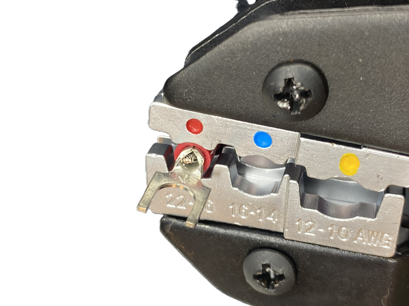
Do not choose the die by colour. Colour codes on crimpers and terminals differ between makers, and some pliers have none. Go by the wire size marked on the die, in mm² or AWG, or in the tool's own table. If your die gives only mm², use the one that covers 0.82 mm².
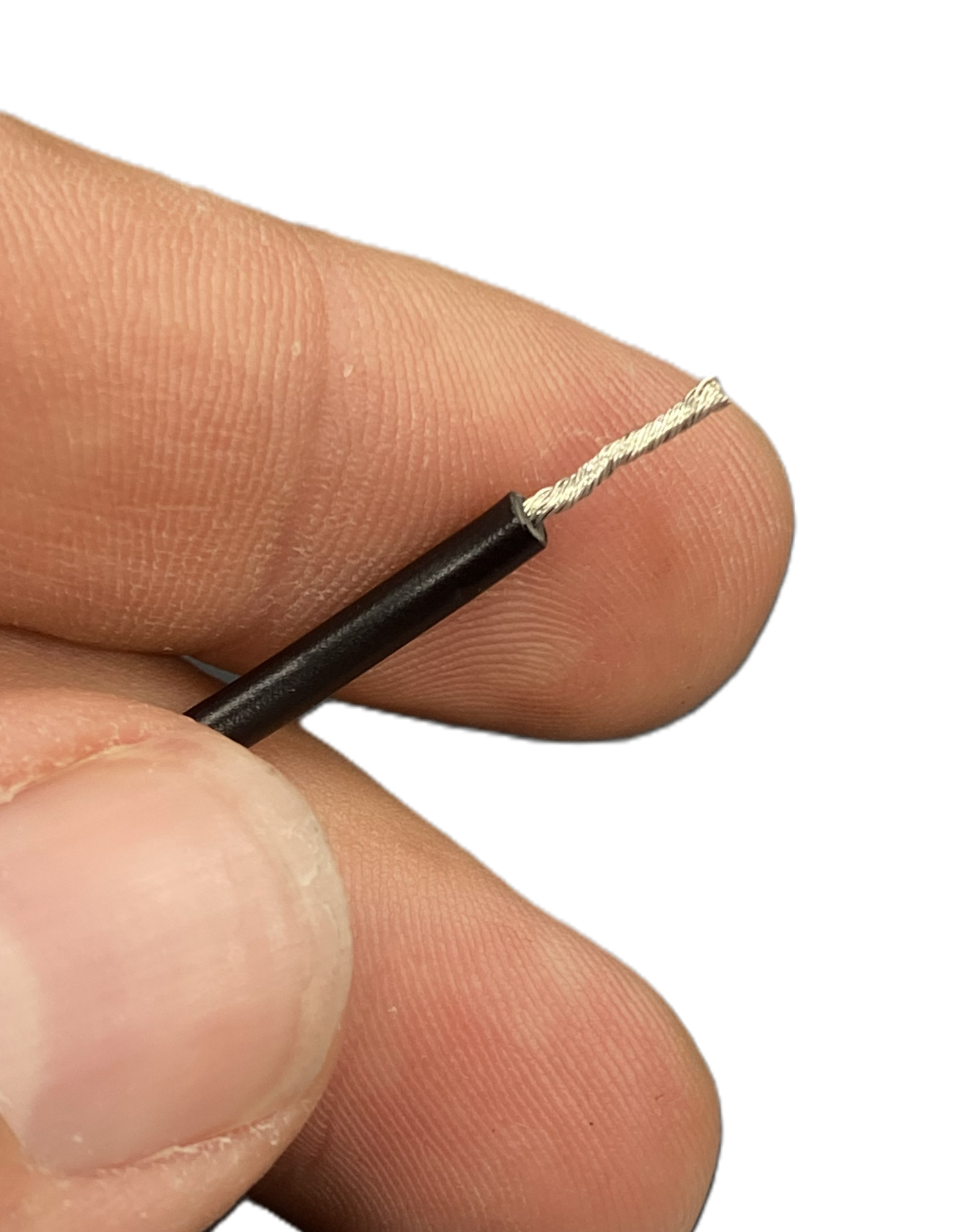
- Hold the terminal against the lead and strip as much insulation as the metal barrel is long.
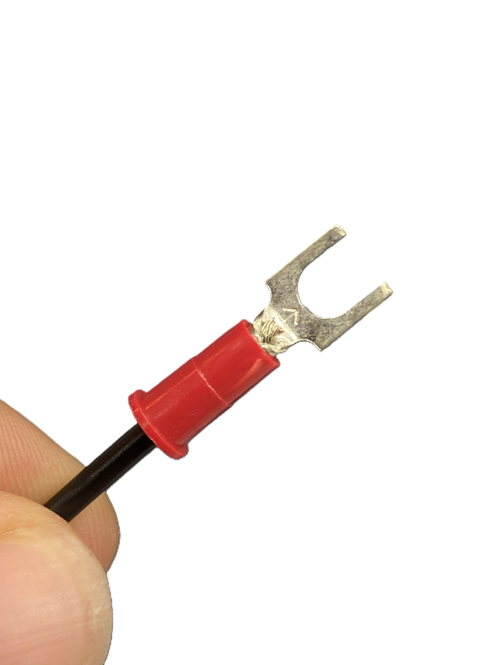
- Push the bare strands into the barrel until they show at its far end and the wire's own insulation reaches the terminal's plastic sleeve.
- Close the terminal in the die marked for 22 to 16 AWG (0.33 to 1.3 mm²). Squeeze until the ratchet releases.
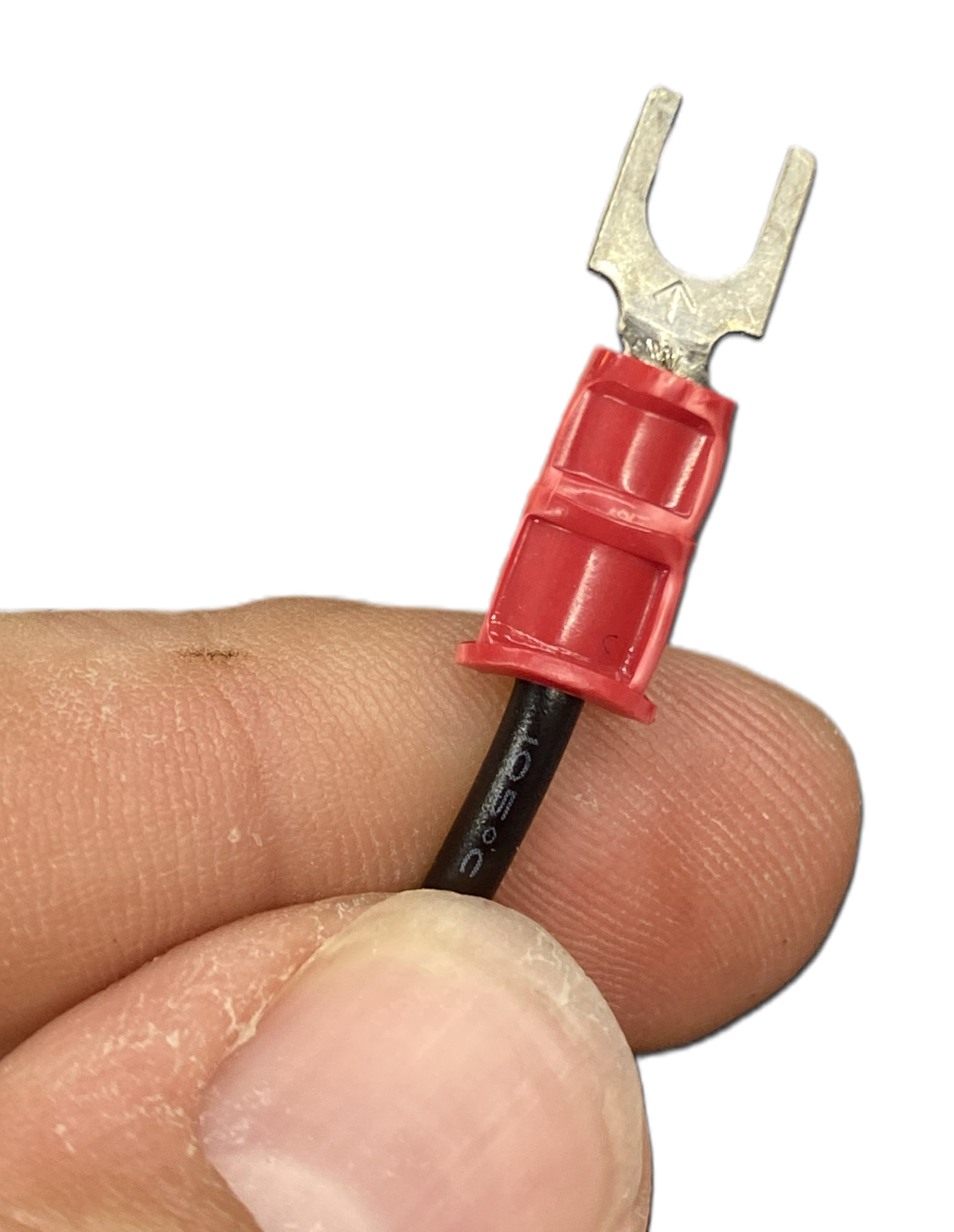
- Pull on the terminal to check it holds.
The finished result
Three pigtails (PJ1 to PJ3), each a panel-mount jack with a fork terminal crimped on both of its leads.

Where it goes
Step 1 of the PSU box: the three jacks push through the connections plate from behind, and the six fork terminals land under the screws of the supply's own terminal block.
Reference
The drawing for this pigtail (PJ1 to PJ3), its bill of materials and its downloads are on the WireViz drawings page.