
Helpers — Control board 24 V lead (W1)
Make the control board's 24 V lead (W1)
How-to guideThe lead (W1) that powers basically board v1.3, a barrel plug at the PSU end and a JST-VH housing crimped on at the board end. One per machine.
Parts needed
Wire harness
- 1×Three per machine, one each on W1, W2 and W3.
- 1×1.22 m a machine, nearly all of it W1.
- 4×Two per lamp, one for each wire of the barrel socket, and two on each of the control board's and the Orange Pi's 24 V leads. Six more are spares.
- 1×The board end of W1. Pin 1 is +24 V.
- 4×Two on W1 and two spares. Crimp onto the wire first, then push into the shell.
- 1×Optional. About 900 mm (35 in) over the pair.
A an interchangeable alternative works (hover for what).
Tools needed
- Side cutters, to cut the pair to length
- Wire strippers, for 18 AWG (0.82 mm²) wire
- Crimping pliers for open-barrel contacts, with a die for 22 to 16 AWG (0.33 to 1.3 mm²), for the VH contacts
- Insulated-terminal crimping pliers with a die for 22 to 16 AWG (0.33 to 1.3 mm²) wire, for the butt connectors on a moulded plug
- Multimeter, to find the tip and to check the finished lead
- A small screwdriver, only for a screw-terminal plug
- Only if you solder a moulded plug's leads instead of crimping them: a soldering iron, solder and adhesive-lined heat shrink (see Getting started)
- Optional, for the sleeving: scissors and tape, or a hot knife
This is the control board's 24 V lead (W1) on the harness drawings. It runs from one of the three jacks on the PSU box to J1, the 24 V input on the control board. One per machine.
This is the one 24 V lead nobody sells ready made. No stock cable has a barrel plug with a JST-VH housing on the other end, so either have a cable assembly vendor make it as part of the harness order, or make it yourself with this page. The other two 24 V leads need no JST housing: one is a barrel plug on the buck converter's wires (W3), the other a barrel plug screwed into the USB hub (W2).
The two ends
- PSU end
- Male DC barrel plug, 5.5 mm (0.217 in) outside and 2.1 mm (0.083 in) inside, centre-positive: the tip is +24 V and the sleeve is ground. A 2.5 mm (0.098 in) plug looks the same and does not mate. It comes as a screw-terminal body you wire yourself or as a moulded plug on a short lead; either works and the step below covers both.
- Board end
- JST VH housing, 2-pin (VHR-2), with a VH crimp contact on each conductor. VH pins are 3.96 mm (0.156 in) apart, so the housing is much chunkier than the 2.0 mm (0.079 in) PH housings the steppers use. The two do not interchange.
- Wire
- 18 AWG (0.82 mm²), two conductor, red and black: red is +24 V, black is ground, the same convention as every other DC lead on the machine. Cut it 920 mm (36 in) long.
No Dupont or PH kit has a VH housing. Your open-barrel crimp tool does take the VH contacts, so the VHR-2 and its contacts in the list above are a separate buy and the same tool crimps them. The list has four VH contacts and four butt connectors, two more of each than the lead uses: the first crimps on a new part are easy to spoil, and a mis-crimped contact cannot be reused.
Build it
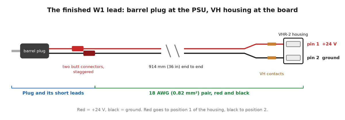
W1), with a moulded plug. A screw-terminal plug has no butt connectors: the pair's wires go straight under its screws.- Cut the 18 AWG (0.82 mm²) pair with side cutters so the finished lead is 920 mm (36 in) end to end.
- Optional: if you will sleeve the lead, slide a 900 mm (35 in) length of braided sleeving over the pair now, before you fit the plug or crimp the VH contacts. A finished plug or housing may not go through it, so it goes on first. Leave it bunched up on the pair for now; Sleeving (optional) says how to cut and finish it.
- Fit the barrel plug to one end. On a screw-terminal plug, strip 5 mm (0.2 in) off each conductor, get the bare strands fully under the screws, tighten firmly and pull on each wire. On a moulded plug on a short lead, join each of its two leads to one wire of the pair with a butt connector. How is under Joining a moulded plug's leads, below.
- Find which conductor is the tip. Set the multimeter to continuity and hold one probe on the centre pin inside the plug. The conductor that beeps is +24 V. Red is the tip on most plugs, but a few are wired the other way, so this is the step where you find out rather than assume. Put a turn of tape on the +24 V conductor at each end, whatever its colour, so you still know which one it is in the steps below.
- Strip 3 mm (0.12 in) off the free end of each conductor.
- Crimp a VH contact onto each. Seat the bare strands fully in the barrel and crimp it in the die of the open-barrel pliers marked for 22 to 16 AWG (0.33 to 1.3 mm²). Then pull on the wire to check it holds. How a contact is crimped, with a picture, is on [Crimping connectors](/hardware/helpers/crimping/).
- Push each contact into the back of the VHR-2 housing until it clicks and will not pull out. The two cavities look identical, so find the right one first: hold the housing with the end the wires will leave from toward you and the raised latch bar on top. +24 V (red) goes in the left cavity, ground (black) in the right. Dab a marker on the housing above the red cavity so you can see which is which later.
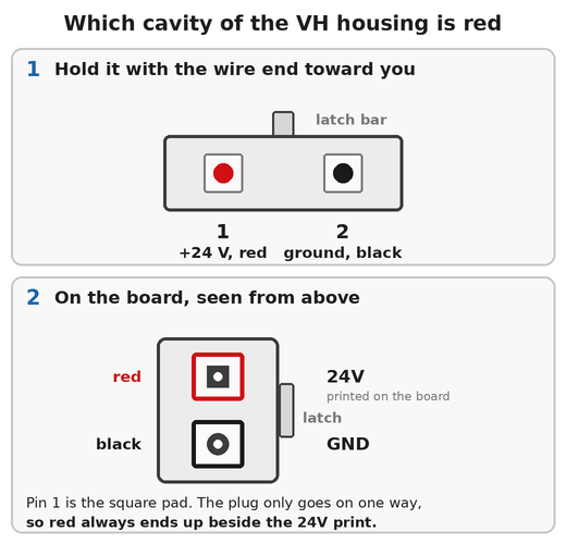
24V print.On the board. J1 is a shrouded header with a slot for the latch, so the housing only goes on one way round, and that fixes which cavity is which. Position 1, the red one, lands on the square pad, beside the 24V printed on the board. The round pad is position 2, beside GND. Check this when you plug it in: the red wire should be on the 24V side.
Joining a moulded plug's leads
Only if your plug is moulded on a short lead. The plug's two leads and the two wires of the pair are joined end to end, one joint per wire, so there are two. Join the plug's red lead to the pair's red wire and its black lead to the black wire. Do one joint at a time so the two never touch.
A butt connector is a vinyl-insulated barrel that takes one wire in each end, rated for 22 to 16 AWG (0.33 to 1.3 mm²) wire. Nothing is soldered.
- Strip 7 mm (0.28 in) off the plug's lead and off the pair's wire, and twist the strands of each tight.
- Push the plug's lead into one end of a red butt connector, and the pair's wire of the same colour into the other, until the insulation of each wire meets the end of the barrel.
- Close each end of the barrel in the die of the insulated-terminal crimping pliers marked for 22 to 16 AWG (0.33 to 1.3 mm²), so each wire is crimped separately. Squeeze until the tool releases. Pull on each wire to check it holds.
- Stagger the two butt connectors by a few millimetres along the lead so they cannot touch.
Use insulated-terminal crimping pliers. A crimp tool for open-barrel contacts, the kind that does the VH contacts, has the wrong die and will not close a butt connector properly.
Check the finished lead
Do this before the lead goes anywhere near the PSU. A lead wired backwards is not something the 24 V input on the board recovers from.
- Set the multimeter to continuity.
- Hold one probe on the centre pin inside the plug and the other on the metal contact in position 1 of the housing. It must beep.
- Hold one probe on the metal sleeve of the plug and the other on the metal contact in position 2. It must beep.
- Hold one probe on the centre pin and the other on position 2. It must not beep. Do the same from the sleeve to position 1.
If a check gives the wrong answer, do not plug the lead in. Find the wire that is in the wrong position or the joint that is bad, and fix it first.
Sleeving (optional)
You can skip this and the lead works the same. The sleeving is on the parts list as optional. It keeps the wires together as one tidy cable and protects them where the lead runs along the frame, and it is another way of securing the cables.
Where: over the pair, from just short of the barrel plug (or of its butt connectors, on a moulded plug) to just short of the VHR-2 housing. About 900 mm (35 in).
How:
- Push the braid together lengthwise to open it: it widens as it shortens. Feed all the wires into it together, so none of them is left outside.
- Cut it to length with a hot knife or a soldering iron with a blade tip, so the cut melts shut. Plain scissors leave the braid fraying. With no hot tool, wrap a turn of tape around the braid where you will cut, cut through the middle of the tape with scissors, and leave the tape on.
- Stop the sleeving 5 to 10 mm (0.2 to 0.4 in) short of the plug, or of its butt connectors, and short of the VHR-2, so the contacts and the housing can flex and the sleeving never crowds into either.
- Hold each end with a small piece of heat shrink or a turn of tape, so that the braid cannot creep back along the wires.
Leave the sleeving loose enough to bend, and do not tie it down so tightly that it crushes the braid.
The finished result
One lead (W1), 920 mm (36 in), with a barrel plug at one end and a 2-pin JST-VH housing at the other.
Where it goes
Onto J1 at connecting the components, step 1. The PSU end goes into any of the three jacks on the PSU box; all three are the same.
Reference
The drawing for this lead (W1), its bill of materials and its downloads are on the WireViz drawings page.