
Feeder — Lamp arm
Lamp arm
How-to guideThe arm and the ring it carries, the reflector with its ring of LED strip, and the cover that goes over the top. The half of a camera lamp that is the same on all three. Build three.
Parts needed
Printed parts
- 1×
- 1×
- 1×
- 1×
- 1×
- 1×
- 6×
- 1×
Wire harness
- 1×About 920 mm of 24 V strip cut from a 5 m roll. One roll does all three lamps.
Screws
- 12× 12mm
Tools needed
- Hex key, 2 mm
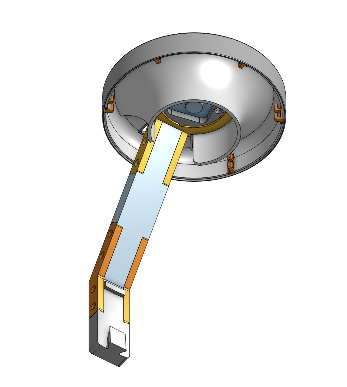
This page builds the part of a camera lamp that is the same on every channel: the arm with its ring at one end and its dovetail at the other, and the shaded lamp that sits over the ring. No camera goes on here. That is the feeder camera lamp page for C2 and C3, and the classification camera lamp page for C4.
The parts list above is one arm's worth. Build three, for C2, C3 and the classification channel. The bulk channel (C1) takes none, because the machine does not look at it.
Prepare an LED strip before you start. One per lamp: a two-turn length cut off the roll, about 920 mm (36 in), with a short pigtail (L1p, L2p or L3p) on the end (ending in a male barrel plug, optional but recommended), either clamped on or soldered. That page has the strip, the connector, the plug and the board cable (L1, L2 or L3); step 4 here only hooks it on.
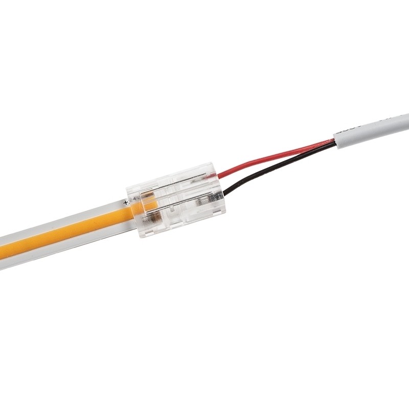
L1p to L3p) that leaves it. Manufacturer photo (SuperBrightLEDs).Fastener icons match the parts list: the silhouette is the head shape, the colour is the thread size. M3 M4 M5 M6
Step 1 Preparation
Colours. The Lamp inner reflector and its six LED hooks print ivory white, and that is not cosmetic: they are the reflector. The Lamp outer cover is ash grey. The arm, the mount, both brackets and the ring follow the channel colour like the rest of that channel's parts.
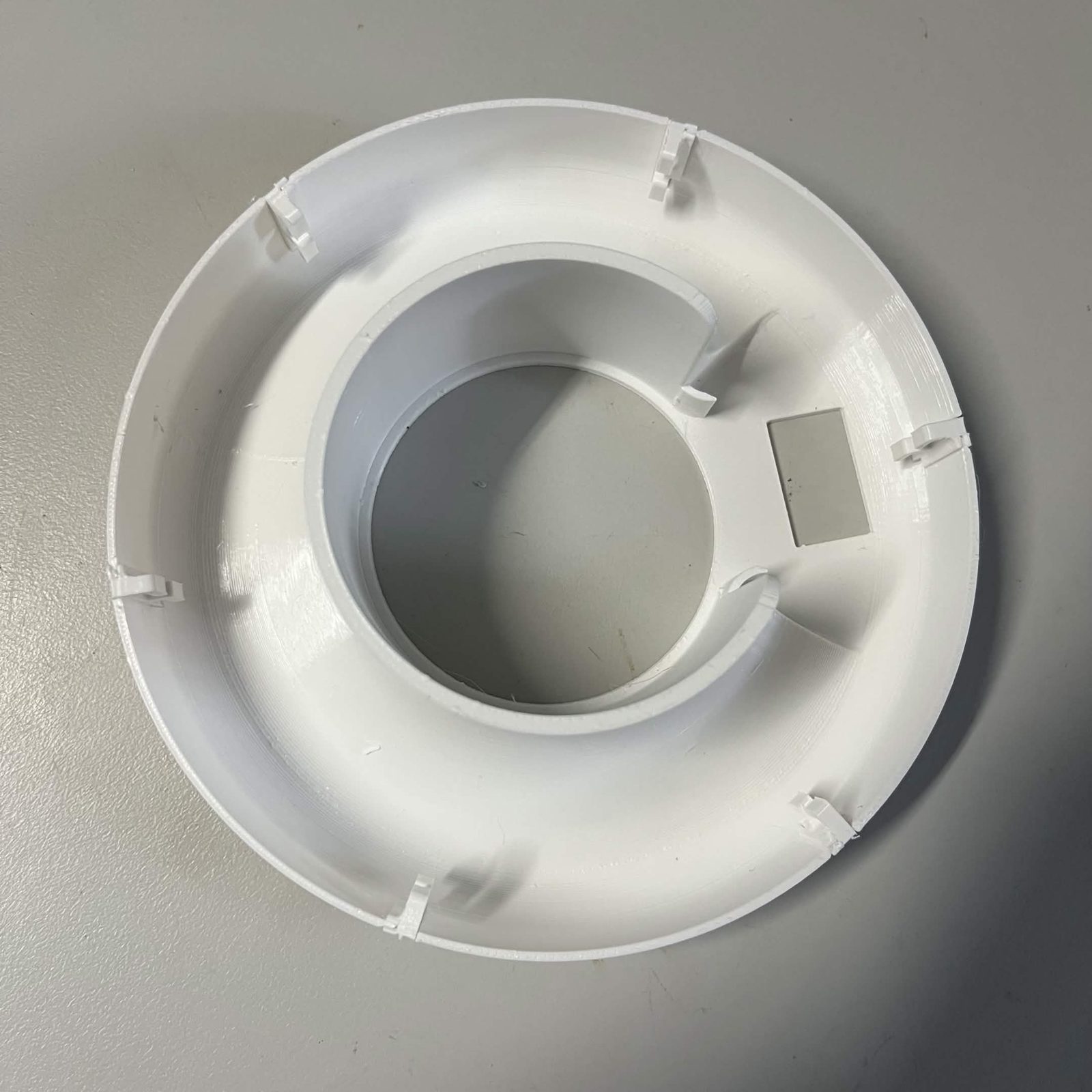
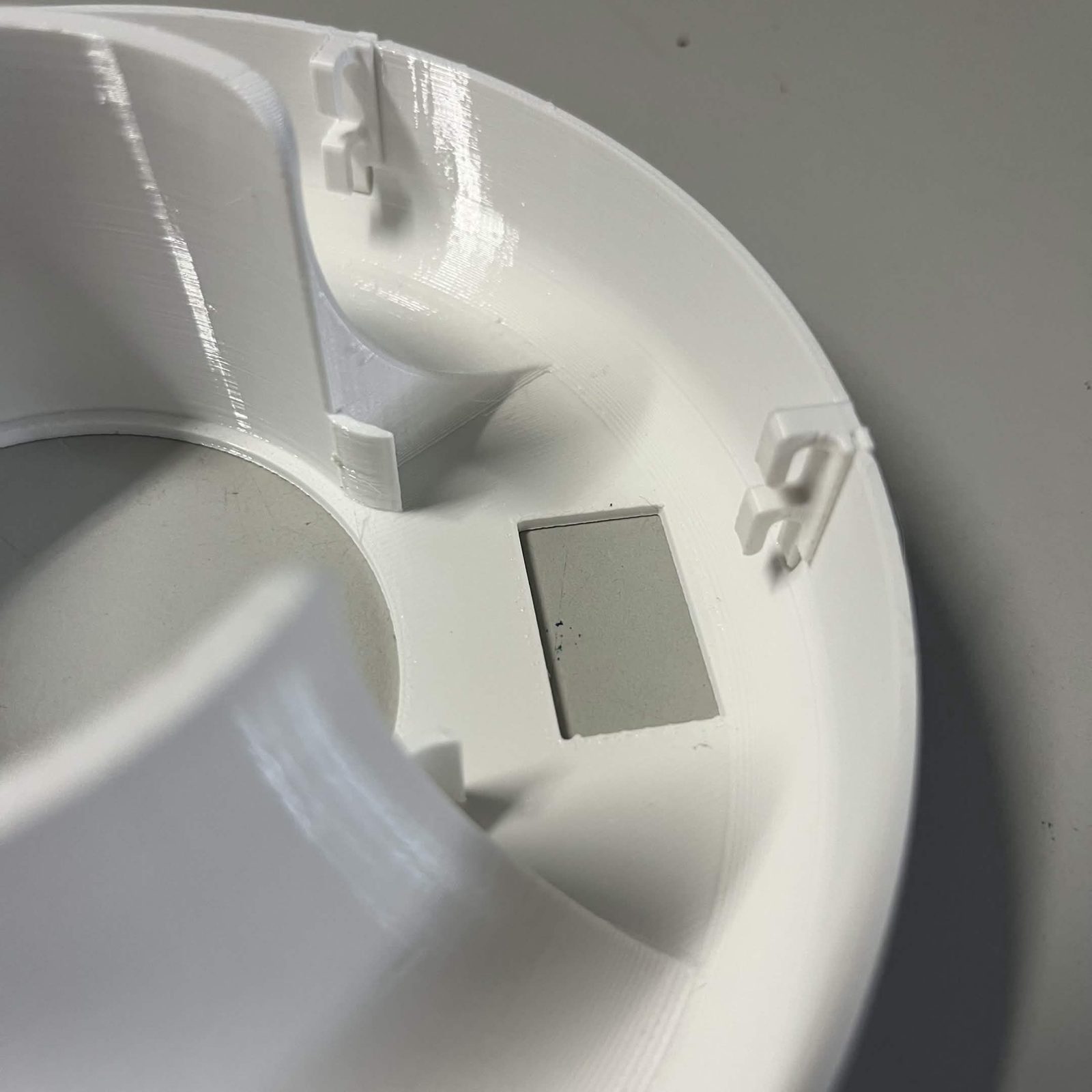
Six LED hooks per lamp, 18 for the machine. They are the ones people come up short on.
Step 2 Bracket the arm to the C-channel arm mount
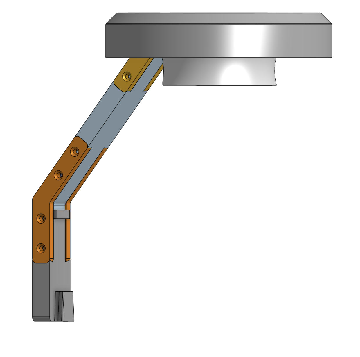
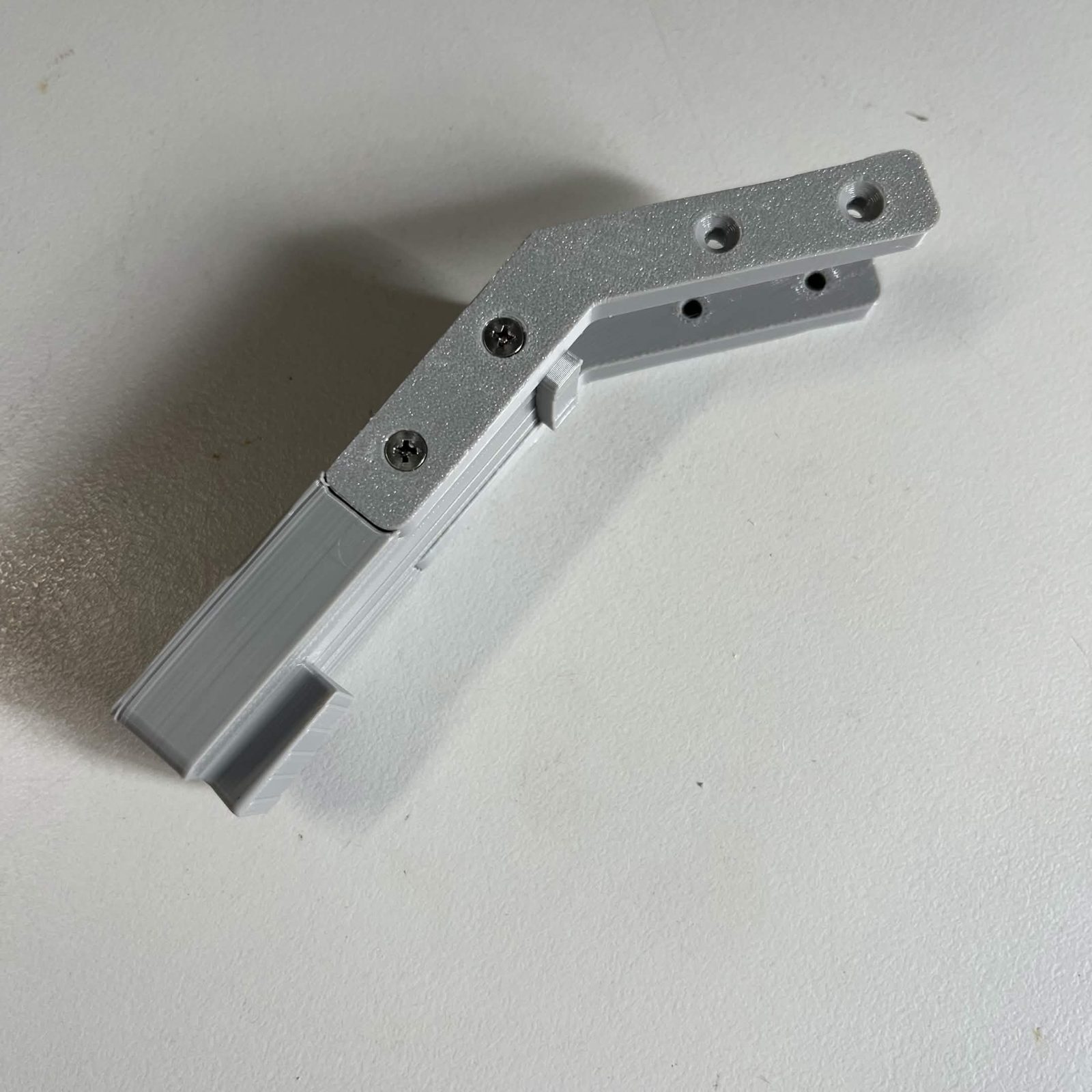
The arm and the mount butt together end to end, with bracket A on one face and bracket B on the other.
- Butt the arm and the mount together. The ends are shaped, so they only mate one way round. If it does not seem to fit, swap the piece end for end rather than forcing it.
- Lay bracket A across the joint on one face and bracket B on the other, angled ends towards the dovetail.
- Drive 8 M3 × 12 mm countersunk screws, four per bracket. Stop as each head seats.
The two brackets share their holes, four holes with a screw into each end, so half of every hole belongs to the other bracket's screw. Use the 12 mm here. Two 16 mm screws would meet inside a hole before either seated.
Step 3 Screw the camera lamp ring onto the arm
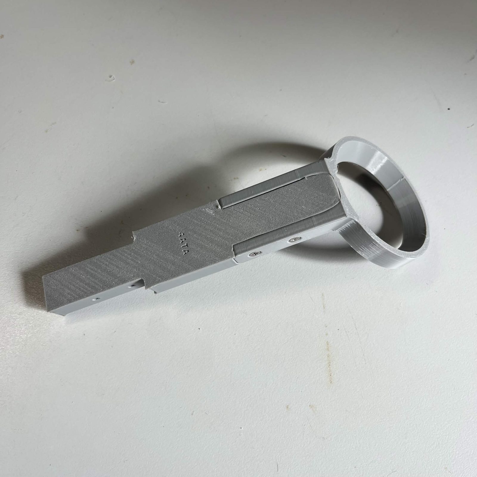
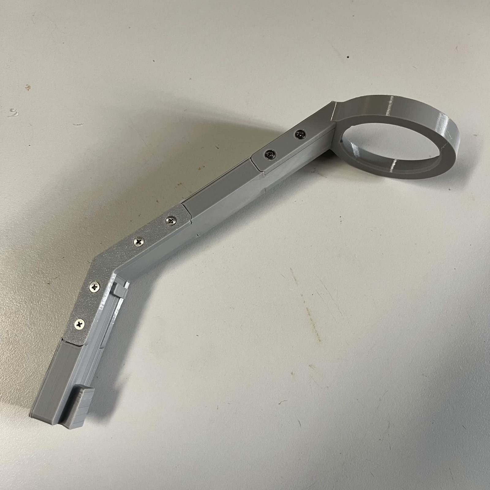
The ring goes on the far end of the arm, and is what the lamp and the camera hang from. It straddles the arm, and it works the same way as the joint below it: 4 more M3 × 12 mm countersunk screws, two per side, into the same two holes.
That is 12 M3 × 12 per arm: 8 at the mount joint, 4 here. Six holes, a screw into each end of every one.
Step 4 Hook the prepared LED strip onto the reflector
Push the six Inner reflector LED hooks into the sockets around the rim of the Lamp inner reflector, evenly spaced. They are a friction fit and there are no screws. Each hook holds the LED strip against the reflector.
The strip itself is cut and wired on Preparing the LED strip: two turns of the skirt, about 920 mm (36 in), cut on a printed mark, with a short pigtail (L1p to L3p) on the cut end, which ends in a barrel plug if you fit the optional but recommended plug and socket. Have one ready before you start this step.
Fitting it. Two turns, LEDs facing inwards.
- Peel the blue film off the first stretch of the strip and start it under one of the hooks, adhesive against the inside of the skirt, with the wired end where you want the leads to leave the lamp.
- Work it round the skirt until you are back where you started. That is one turn.
- Drop down to the next clips and go round again for the second turn, peeling the film as you go.
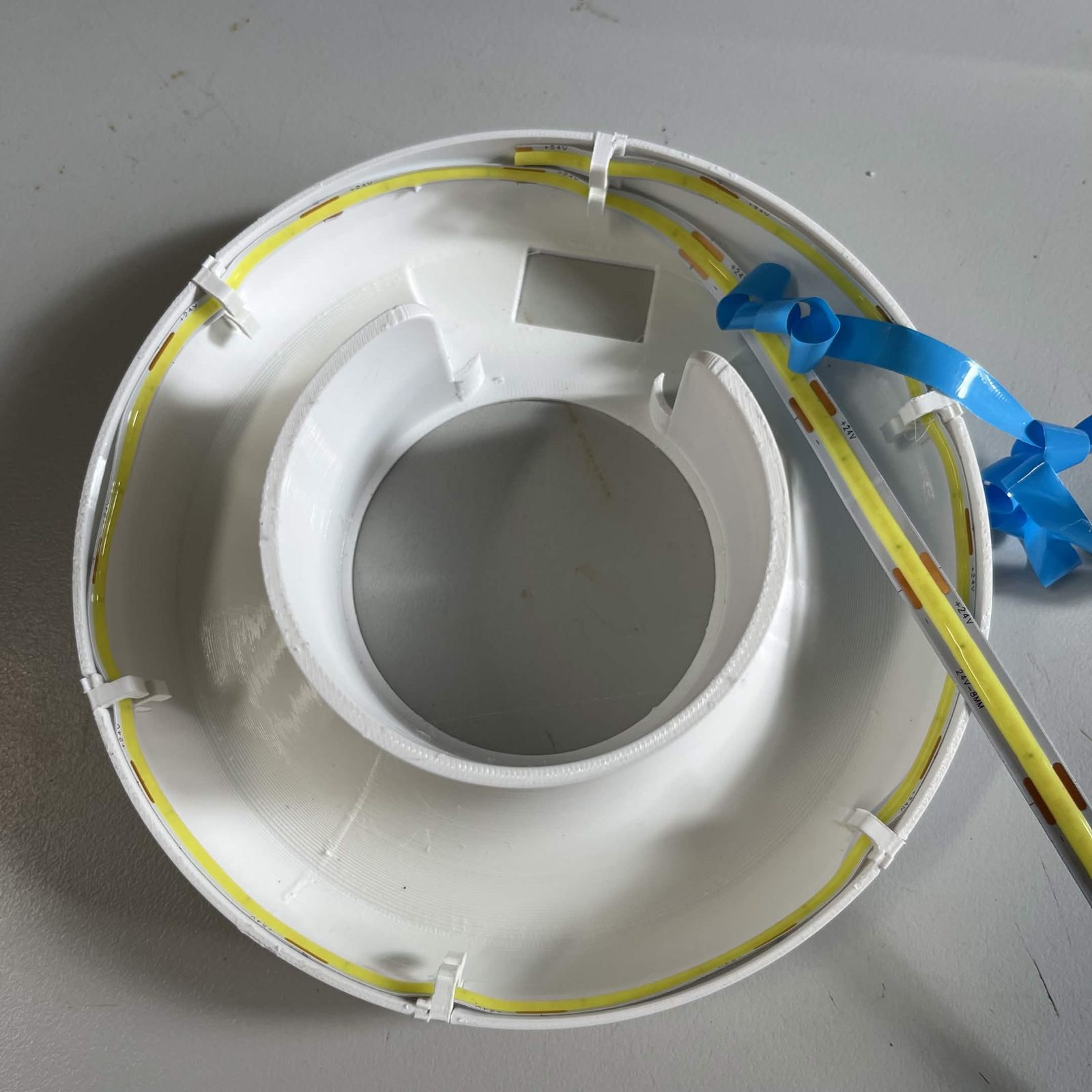
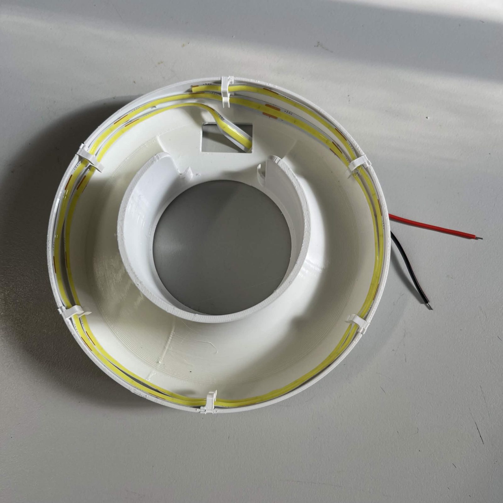
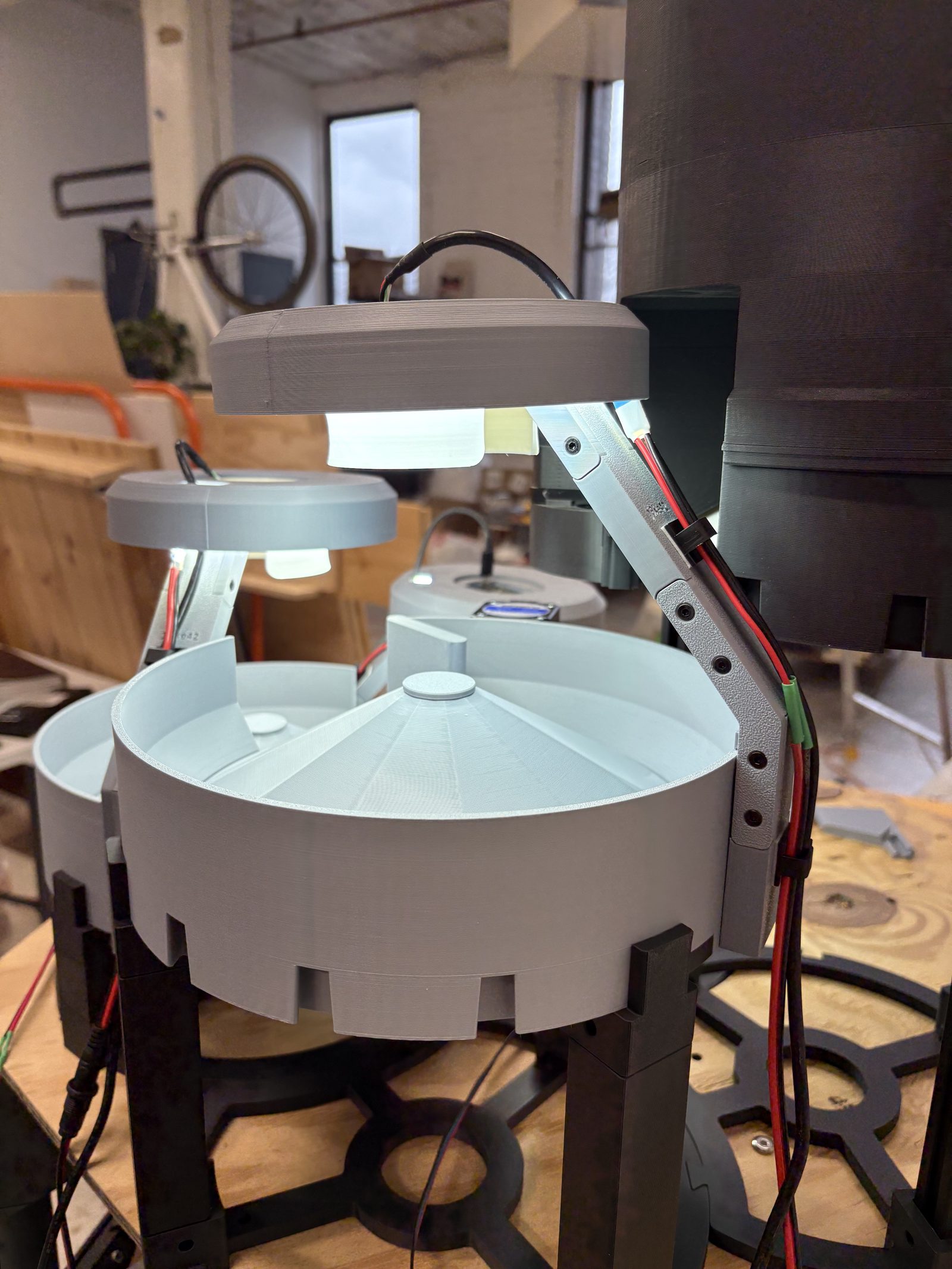
Nothing fastens the reflector to the arm. The arm's ring pushes up into the middle of the reflector from underneath and is held by the fit alone. That happens on the camera page for your channel, with the camera already clasped in the ring, so the arm and the lamp stay separate until then.
The strip comes with its pigtail (L1p to L3p) already on it from Preparing the LED strip; strap that lead down the arm so it is not hanging in the channel (hook-and-loop straps rather than zip ties, see securing the cables). It can leave the lamp two ways, and machines have been built both: straight out of the bottom of the shade, or up through the slot in the cover and down the outside alongside the camera lead. Whichever you pick, keep the run clear of where the strip's own joint sits inside the shade. Plugging it into the board is step 4 of connecting the components. Nothing is joined end to end here, so the far end of the strip stays dead. The strip runs at 24 V off the basically board.
Step 5 Press the outer cover onto the reflector
The Lamp outer cover pushes down over the reflector. It is a friction fit and has no screw hole anywhere. Put the reflector flat on the table, sit the cover on it and press straight down until it seats. It stands slightly proud of the reflector, so the camera clasp ends up recessed in the opening at its centre.
The lamp is finished here, and it is finished without a camera. The camera goes into the ring on the arm, and the arm goes up into the underside of this lamp, on the camera page for your channel. The cover stays on while that happens: the clasp is wider than the opening in the middle of the cover, so the cover overlaps its rim and is what holds the camera down once the arm is home.
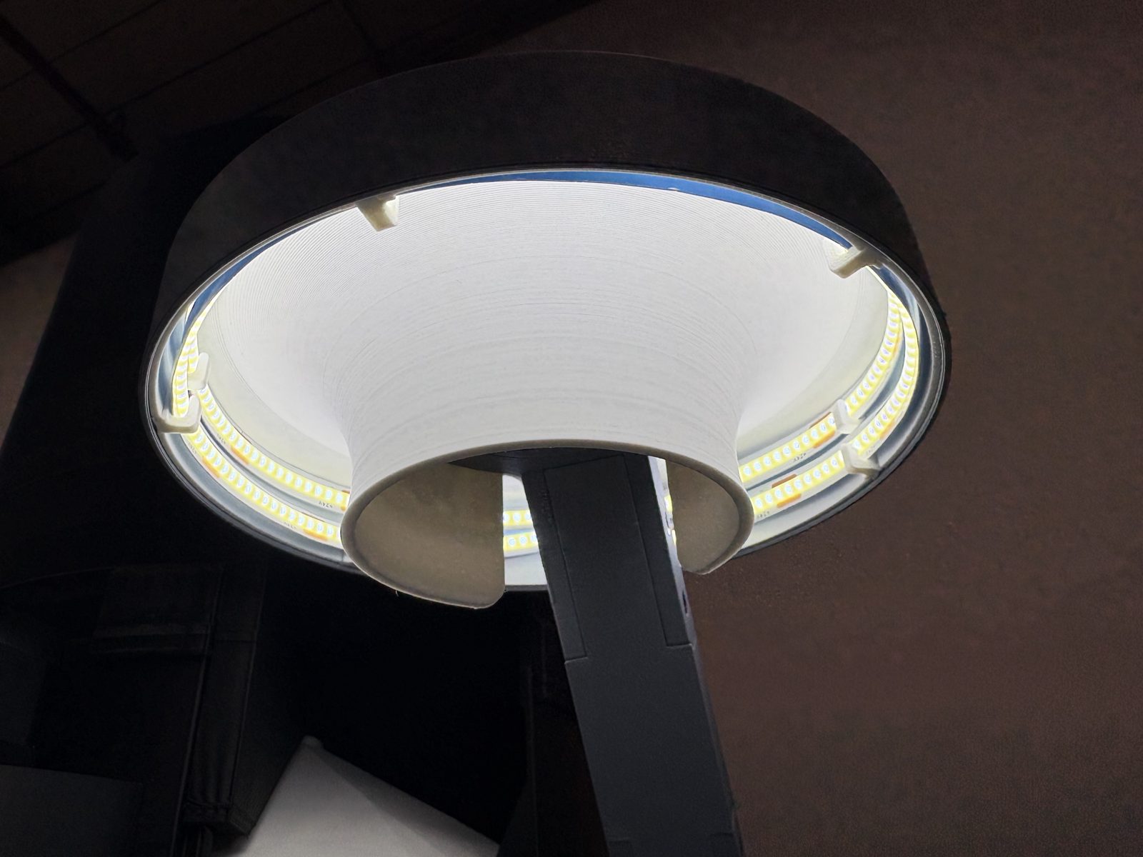
The finished result
An arm with its dovetail at one end and its ring at the other, plus a finished lamp: reflector, LED strip and cover. Build three of each, and take them to the camera page for the channel they belong to, where the camera goes in the ring and the arm goes up into the lamp.
Back to Camera lamps.