
Chute — Layer connectors
Layer connectors
How-to guideThe connectors that chain layers together.
Parts needed
Printed parts
- 1×
- 1×
Screws
- 4× 8mm
Tools needed
- Hex key, 2 mm
The layer connectors are a pair of printed parts, Layer connector A and Layer connector B, that join one layer's chute to the next one down so parts pass from chute to chute without a gap.
The fasteners and quantities are in the parts list above and are called out inline at each step.
Fastener icons match the parts list: the silhouette is the head shape, the colour is the thread size. M3 M4 M5 M6
- How many: 1 of each per distribution layer, plus 1 of each for the bottom interface. For an N-layer machine, that's N + 1 pairs total. The top interface carries none of its own: it lands on the pair already standing on the topmost chute.
- Screws: 2 M3 × 8 mm countersunk per connector, 4 for the pair, in the list above. They go into the inserts of the parts at each end of the joint, not into anything on this page.
- Both connectors go into M3 heat inserts: one screw into the part they are mounted on, one into the part that slots on above.
Step 1 Fit the connectors to the chute core
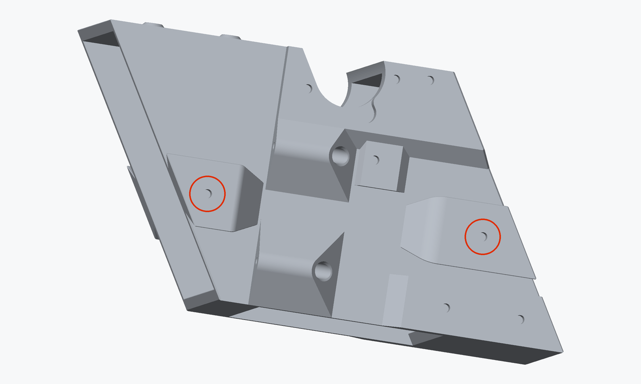
Both connectors fasten to the chute core, into its M3 heat inserts.
Fit one pair to the top of each chute core, and one pair to the top of the bottom interface. Nothing goes on the underside of anything. As the tower goes up, the part above slots down onto the pair already standing on the part below.
Each connector has 2 holes in its strap, one at each end, and takes 2 M3 × 8 mm countersunk screws. Only the lower one goes in now, into the core's own insert; the upper hole stays empty until the part above slots on and is screwed down into it. Don't fully tighten either: step 2 covers checking the alignment first.
The strap is countersunk on its outer face, so the head sits flush. Use the 8 mm, not the 12 mm.
Step 2 Check the alignment against the layer below
Build the layers up first and check that A on one layer sits flush against B on the layer below, with no visible gap or twist between the two straps, before tightening either one down. Nothing here is adjustable once the tower is stacked.
The finished result
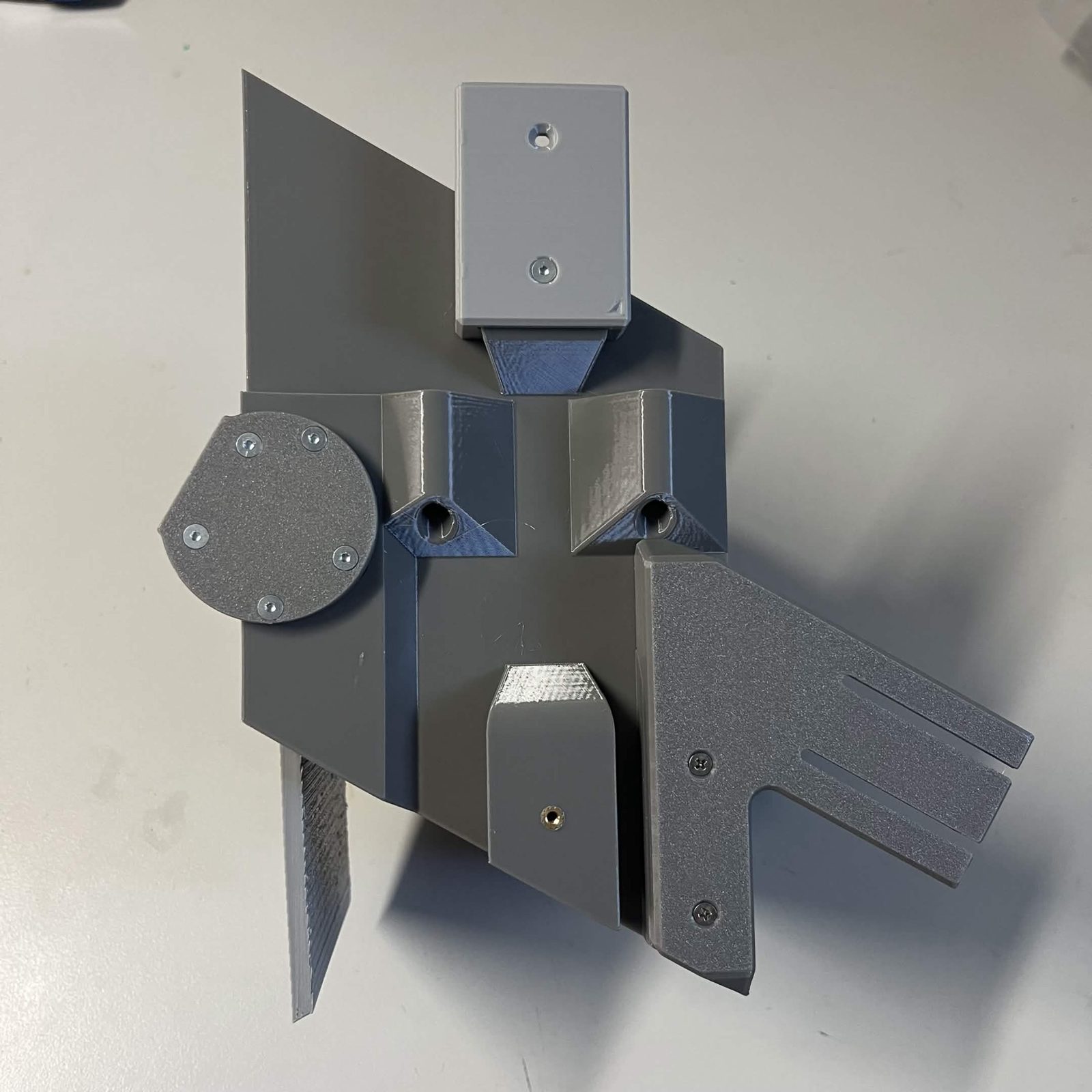
Both connectors on the top of the core, each held by its lower screw, each upper hole left empty for the part that slots on above.
The Chute core page carries the other three sub-assemblies that go on the same core, and is where you should return once you're done here.