
Feeder — Feeder channels
Feeder channels (C2 and C3)
How-to guideThe two metering stages between the bulk channel and classification, with a faceted rotor and an output guide each.
Parts needed
Printed parts
- 1×The feeder channels' rotor.
- 1×
- 1×
Bearings
- 1×
Screws
- 6× 12mm
Tools needed
- Hex key, 2 mm
Build a channel core before you start. This page turns one core into C2 or C3. It does not build the core.
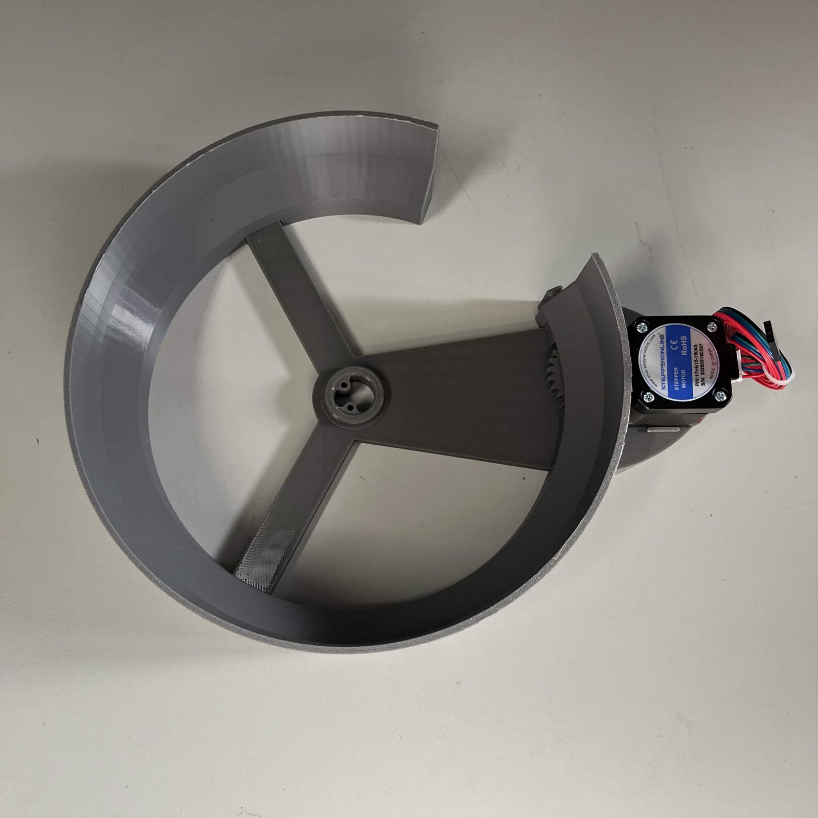
C2 and C3 are the two metering stages. Each takes a part from the channel above, spaces it out further by rotation, and pushes it off its exit to the next channel down.
The parts list above is one channel's worth. Build two, one for C2 and one for C3. They are the same build. Only the height differs, and that is set on arranging C-channels.
- The faceted rotor, the same one C1 takes. It takes no Rotor cap.
- One output guide each, two in the machine. The guide belongs to the channel it is mounted on, not to the gap between two.
- A camera lamp hangs over each of these two. It goes on at arranging C-channels, with the channel standing.
Fastener icons match the parts list: the silhouette is the head shape, the colour is the thread size. M3 M4 M5 M6
Step 1 Preparation
Output gear (130T): press the 6806-2RS bearing into it. No screw, no glue, no heat.
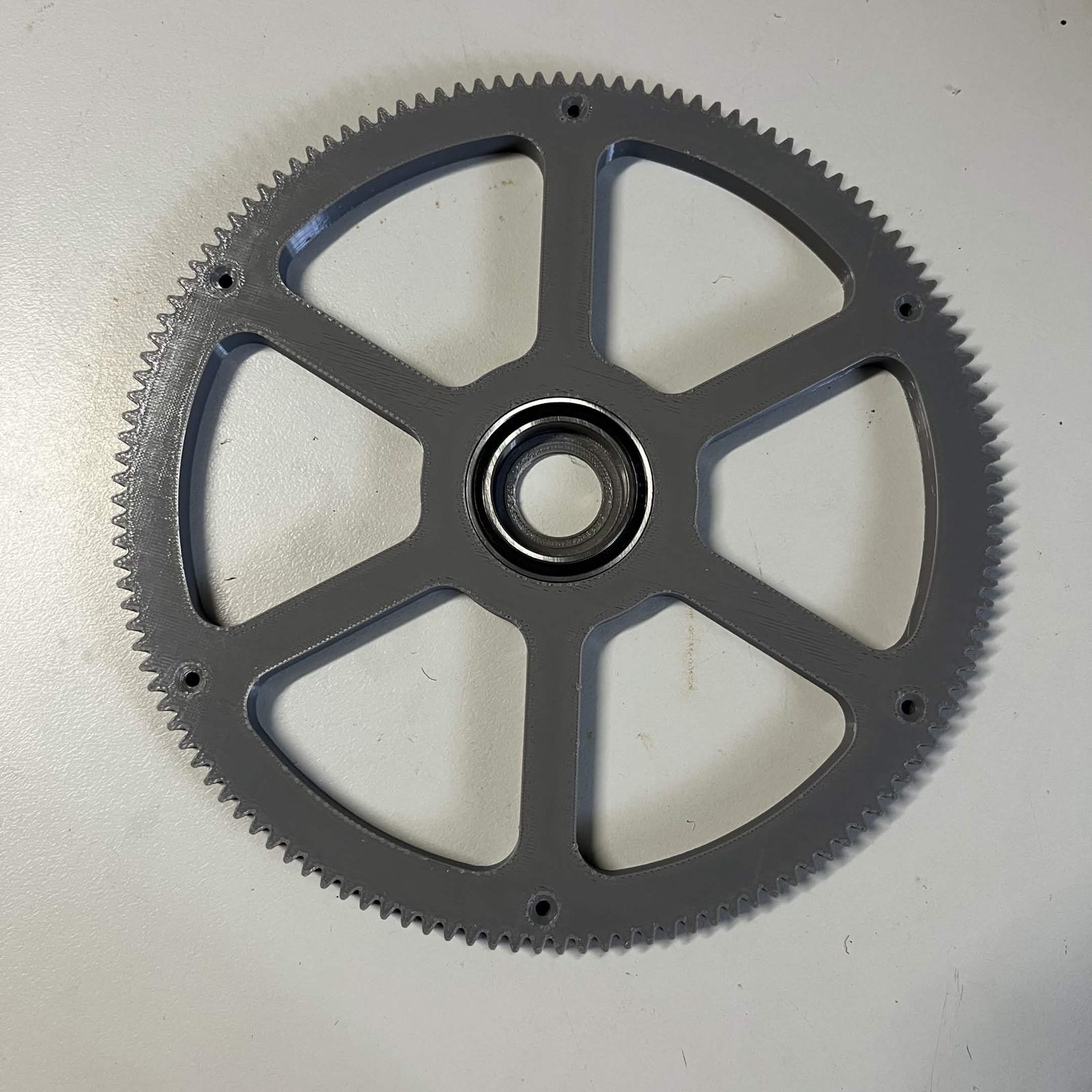
Step 2 Bolt the output gear to the rotor
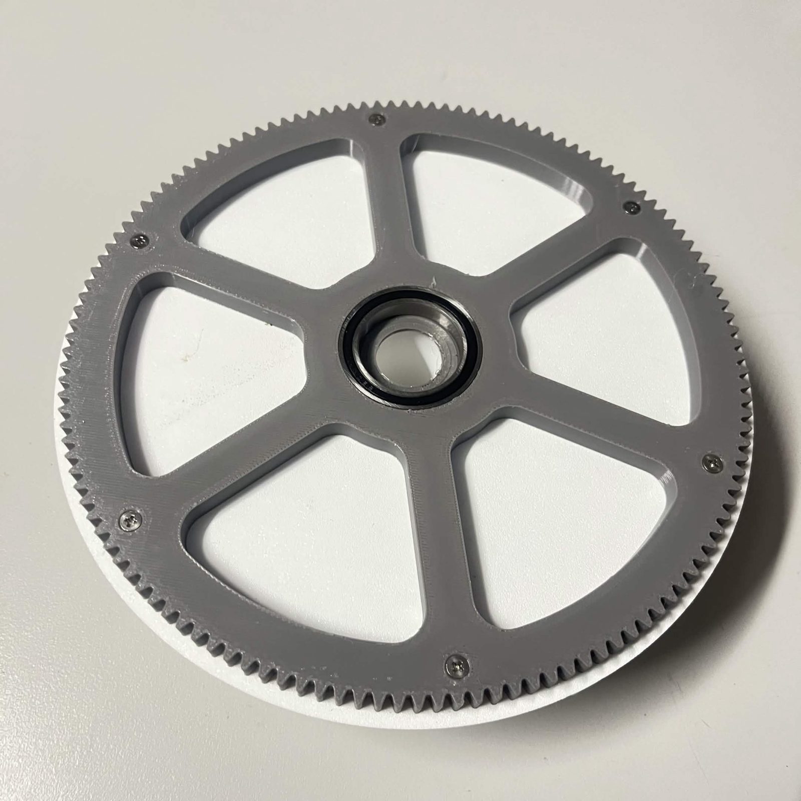
The Output gear (130T) bolts to the open side of the Rotor (faceted).
- Turn the rotor so its open side faces up.
- Put the gear on it and line up the six holes. If it does not sit flat, turn it over.
- Drive one M3 × 12 mm countersunk screw at the outer end of each of the gear's six spokes, until the head is flush in the countersink.
It does not matter which way round you turn the gear. The six holes are the same all the way round.
Step 3 Drop the rotor into the core
Lower the rotor onto the raised hub in the middle of the NEMA bracket. The output gear meshes with the idler as it goes down.
Turn the rotor by hand. It should go all the way round without a tight spot.
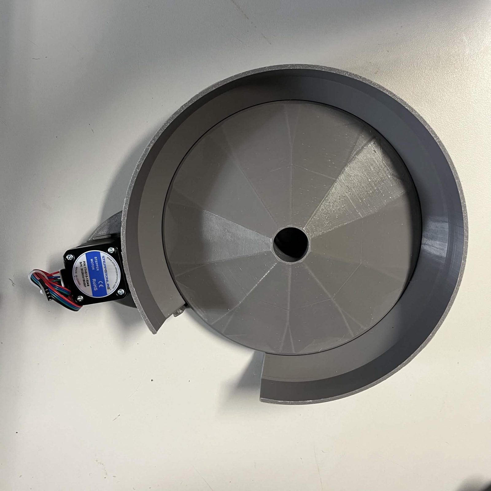
Step 4 Fit the output guide
The guide is a wall at the channel's exit. Without it, a part that does not drop off rides round the rotor again.
Push the guide onto the dovetail on the stator wall beside the NEMA bracket, so it stands in over the rotor just before the exit opening. It is held by the fit alone: no screws, nothing to tighten.
The finished result
A channel core with the faceted rotor in it and an output guide beside the NEMA bracket. Build two. The camera lamp goes on later, at arranging C-channels.
Back to C-channels.