
Chute — Door module
Door module
How-to guideThe per-layer door mechanism that releases parts into a bin.
Parts needed
Printed parts
- 1×
- 1×
- 1×
- 1×
- 1×
- 1×
- 1×
- 1×
- 1×
- 1×
- 1×
- 1×
Motors
- 1×
- 1×
Bearings
- 2×
Heat inserts
- 16×
Screws
- 5× 12mm
- 21× 8mm
Tools needed
- Hex key, 2 mm
- Soldering iron or heat-set insert press
The door module is the moving half of the chute. Build it on the bench as one unit, then bolt it to the chute core. One per chute, so one per layer.
The door pivots on two bearings held in the bearing assembly. The MG995 servo, coupled through the two-piece servo adapter, swings it between its open and closed positions, and the layer's layer adapter board controls when it opens, releasing the part only once the chute stack has rotated the funnel into position over the right bin.
The fasteners and quantities are in the parts list above and are called out inline at each step.
Fastener icons match the parts list: the silhouette is the head shape, the colour is the thread size. M3 M4 M5 M6
Four things make it up:
- Chute door. The flap itself, one printed part.
- Bearing assembly. What the door swings on: the bearing race, a bearing holder (left) and a bearing holder (right), a bearing cover (covered side) and a bearing cover (servo side), and two 6704-2RS bearings.
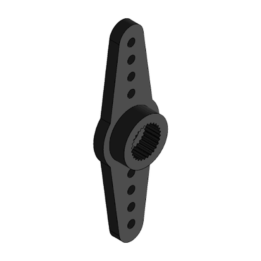
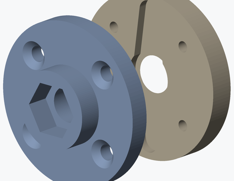
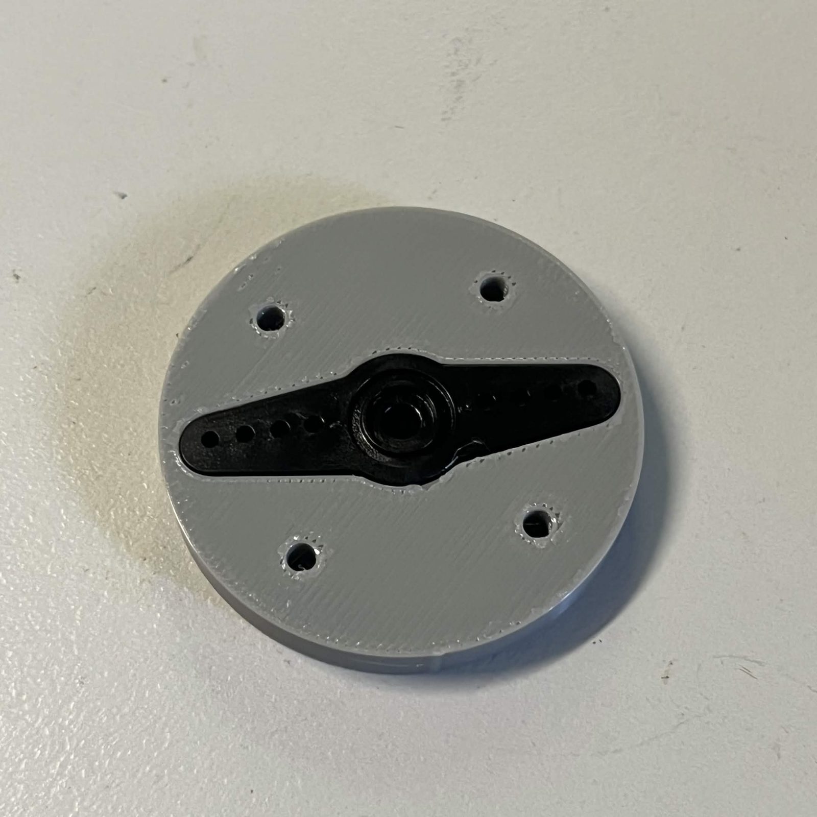
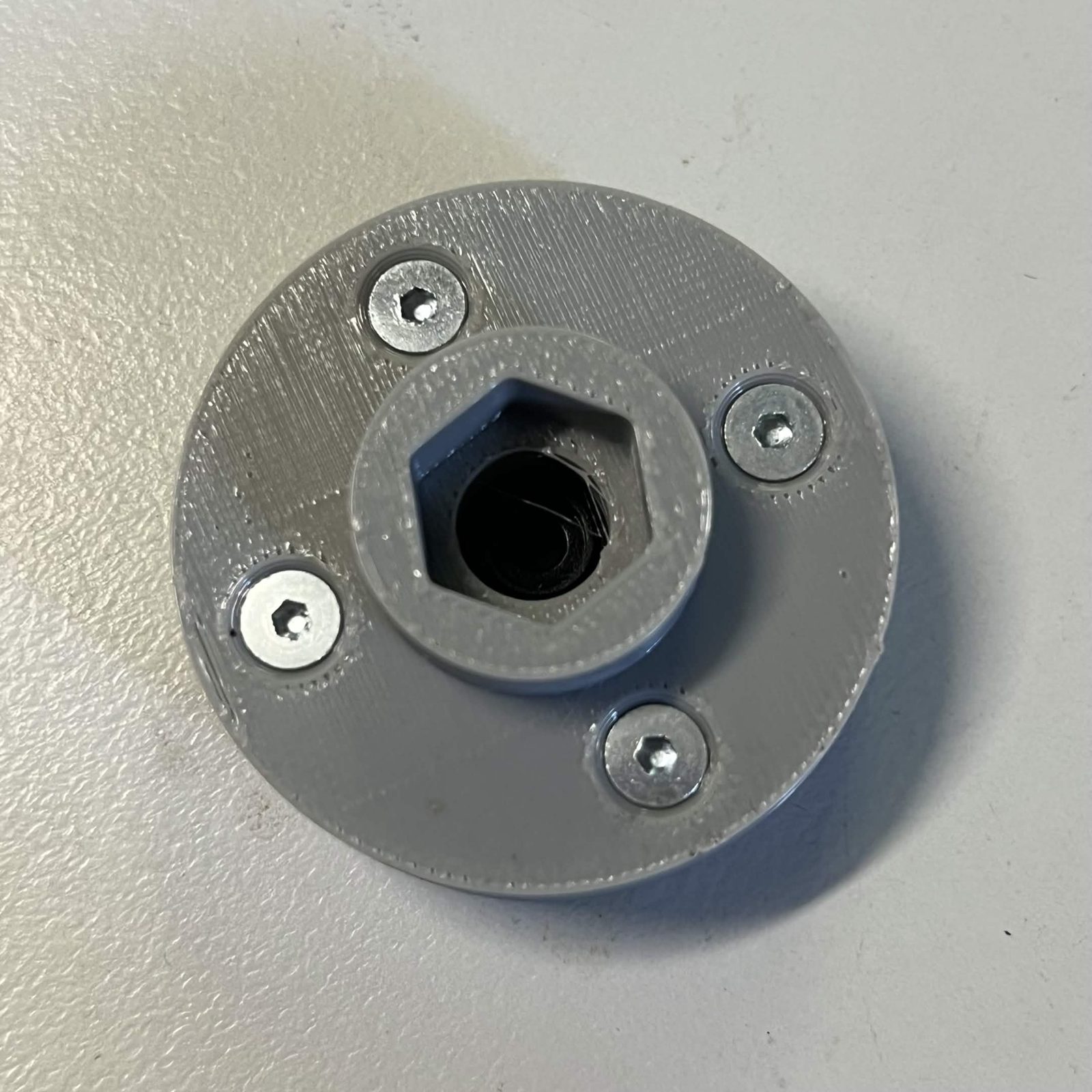
- Servo adapter. Two printed parts, a servo side and a flap side, that couple the servo's output to the door. The MG995 Servo Horn that comes with the servo is clasped between the two halves, then the halves are screwed together around it: 4 M3 × 8 mm countersunk screws, driven through the flap side (it's the half with the visible screw holes) into the servo side.
- MG995 servo in its four-part bracket: a housing, a lower arm, a side arm and a cover. Built on the bench, in the steps below. The servo itself is not screwed to anything. It slides into the housing and the cover goes on over it, and the cover's two screws clamp the servo's mounting tabs in place.
Step 1 Preparation
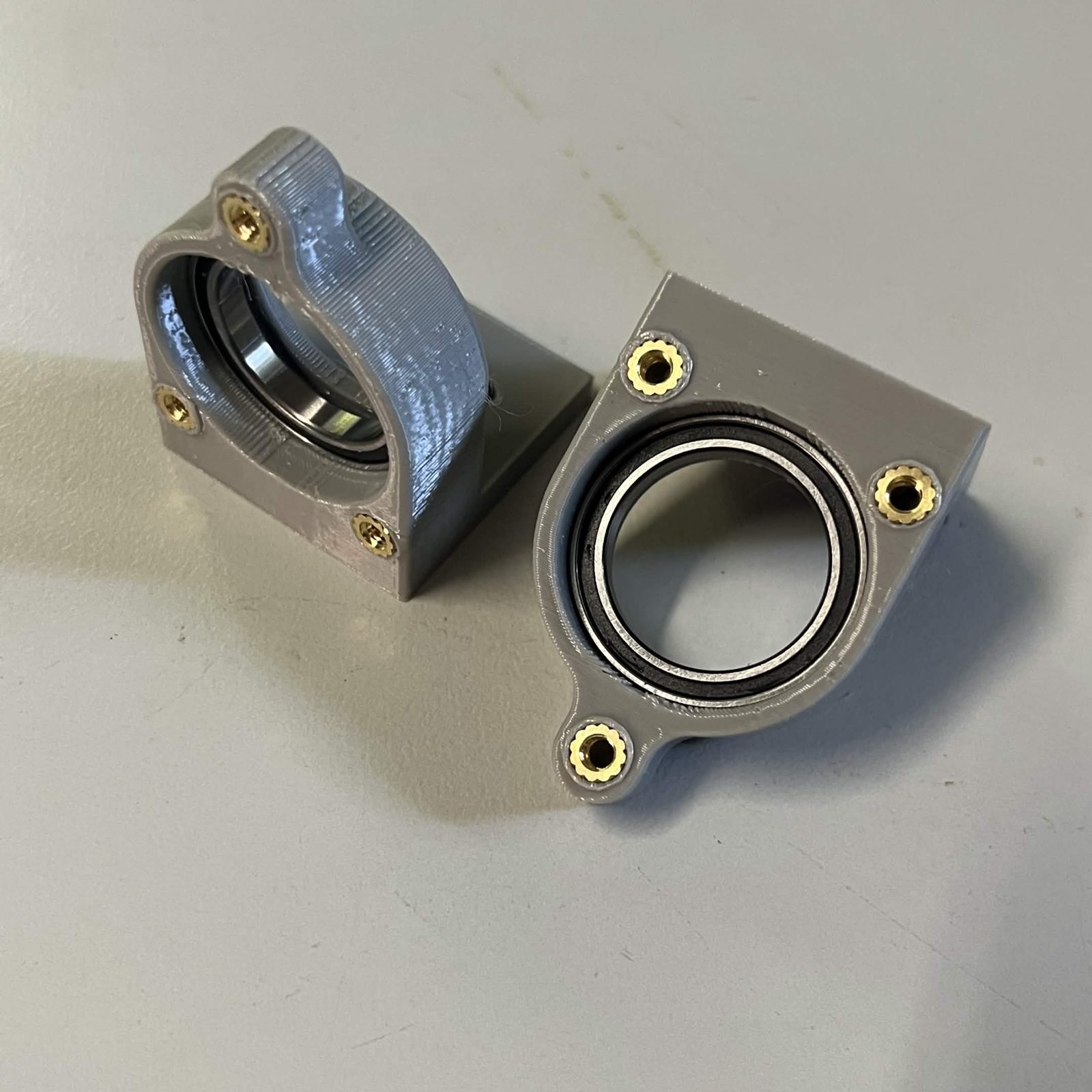
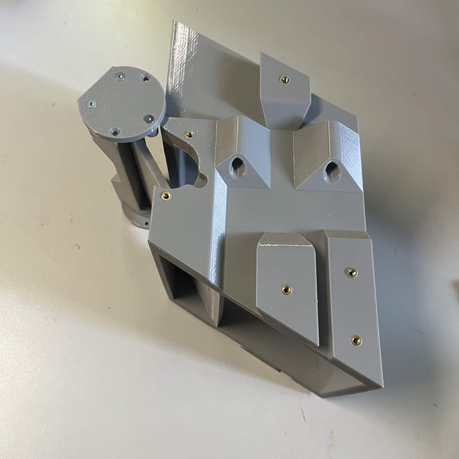
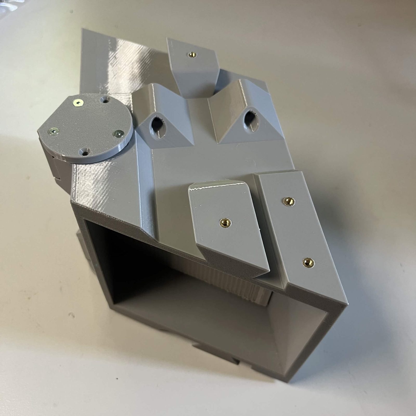
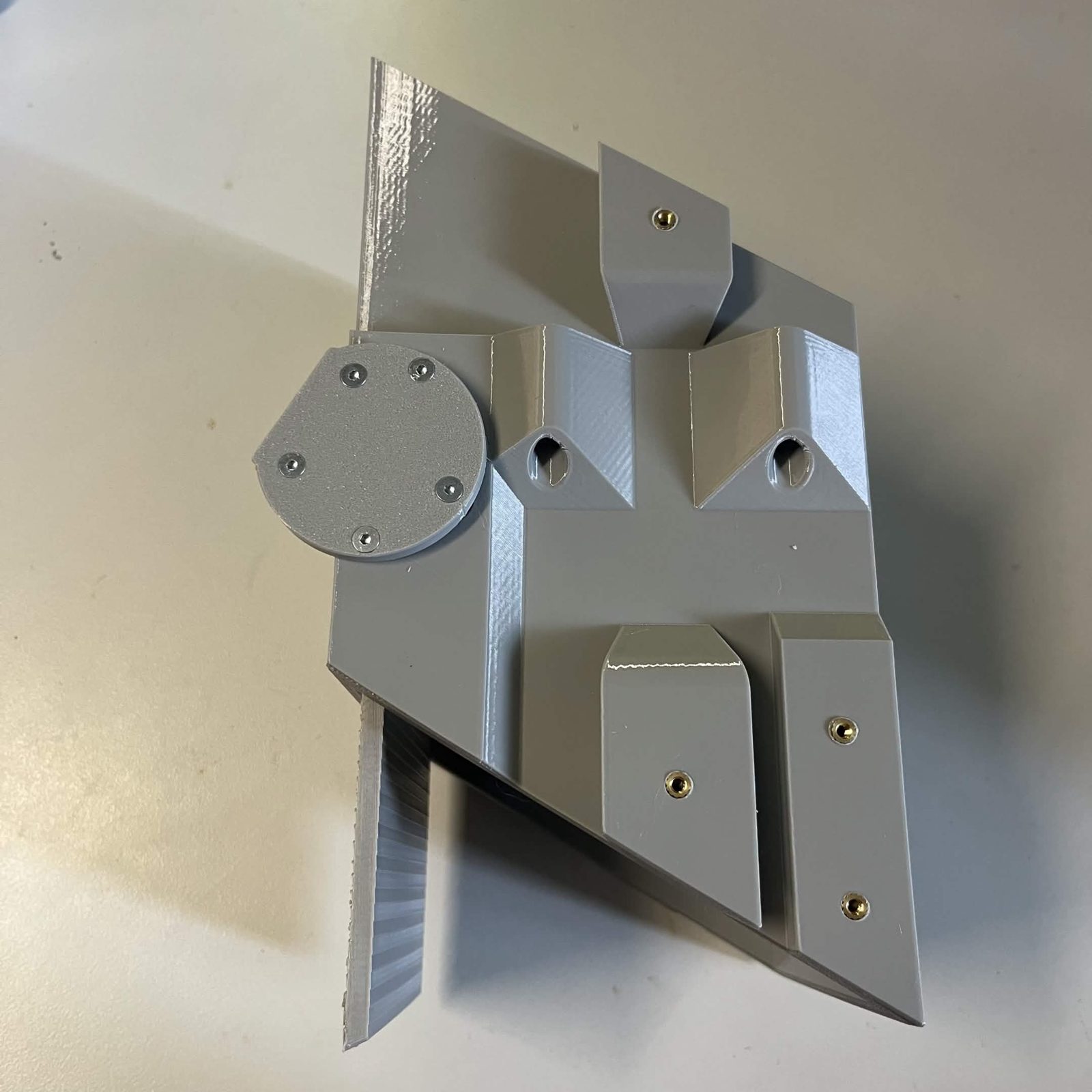
Four of the module's parts take heat inserts, 16 between them. Press them all in while the parts are still bare, before anything is screwed together. See installing heat inserts for the technique.
The two bearing covers, the chute door and the two servo adapter halves take none.
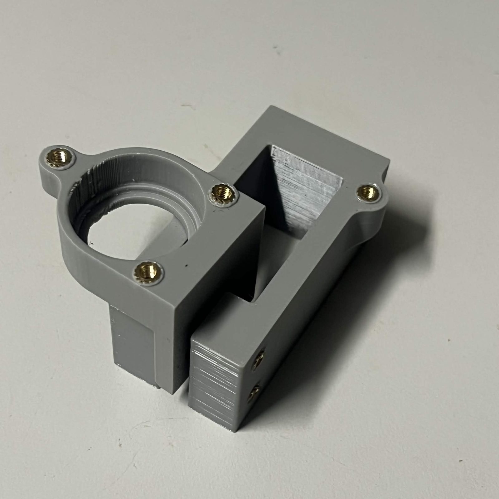
Servo bracket (housing): 6 × M3, two on each of three faces. 2 take the lower arm, 2 take the side arm and 2 take the cover. The servo does not screw to the housing at all, so none of these is for it.
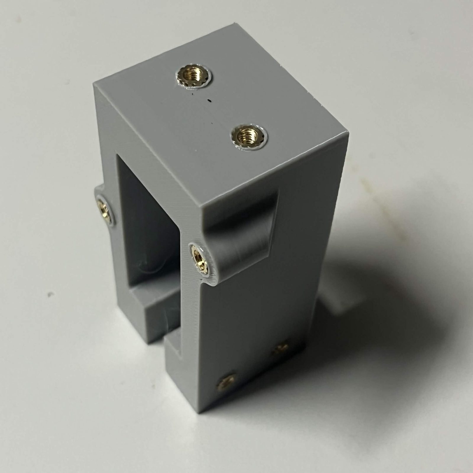
Bearing race: 4 × M3, two at each end. These are the ones the holders screw down onto.
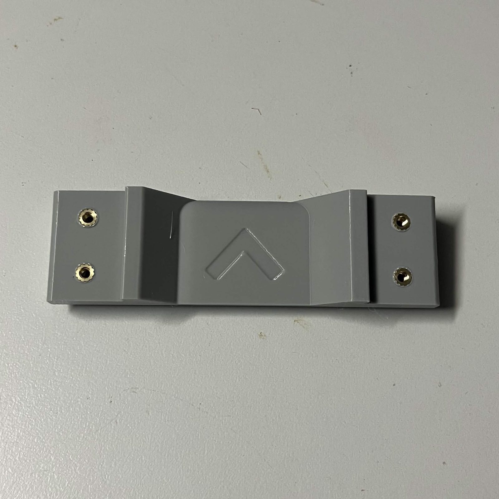
Bearing holder (left) and bearing holder (right): 3 × M3 each, 6 between them, on the outboard face around the bearing bore.
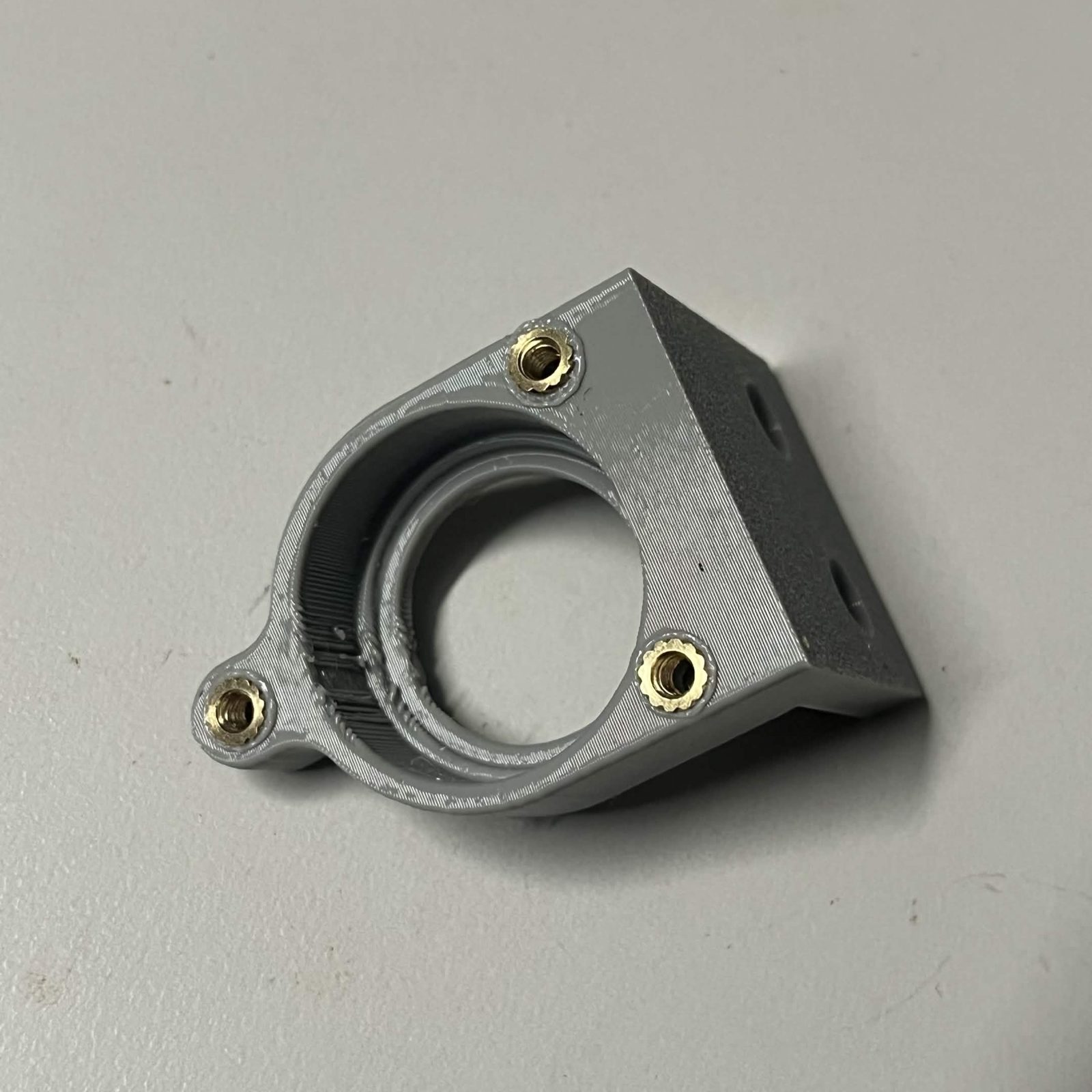
The photos are of printed parts with the inserts already pressed in, one part at a time, so the brass is what you count.
No bench vice? Stand a bearing holder in the servo bracket housing while you press its inserts. The housing's pocket holds the holder upright and square, and leaves both your hands for the iron. Tip: BrickCycleAlice.
One more sub-assembly goes together here, before the step that uses it, and it takes no inserts.
The two 6704-2RS bearings: one into the bearing holder (left), one into the bearing holder (right). There is no wrong way round. Push each one square into the bore until it stops. Home is not the bottom of the pocket: the bearing comes up against a small lip inside the bore and sits proud of the floor, so stop when it stops rather than pushing for flush.
Step 2 Slide the servo into the housing and close it with the cover
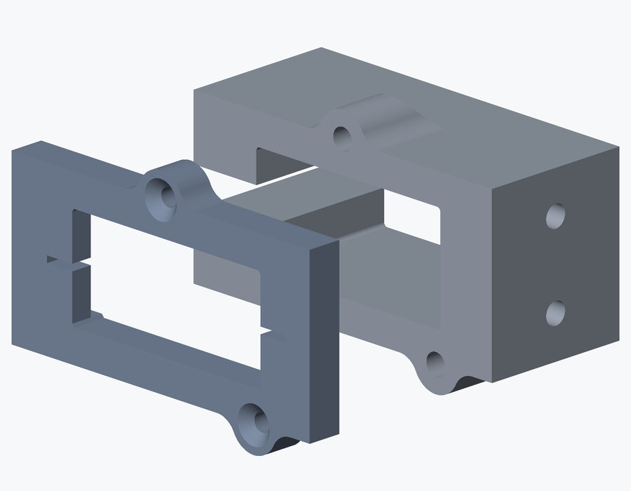
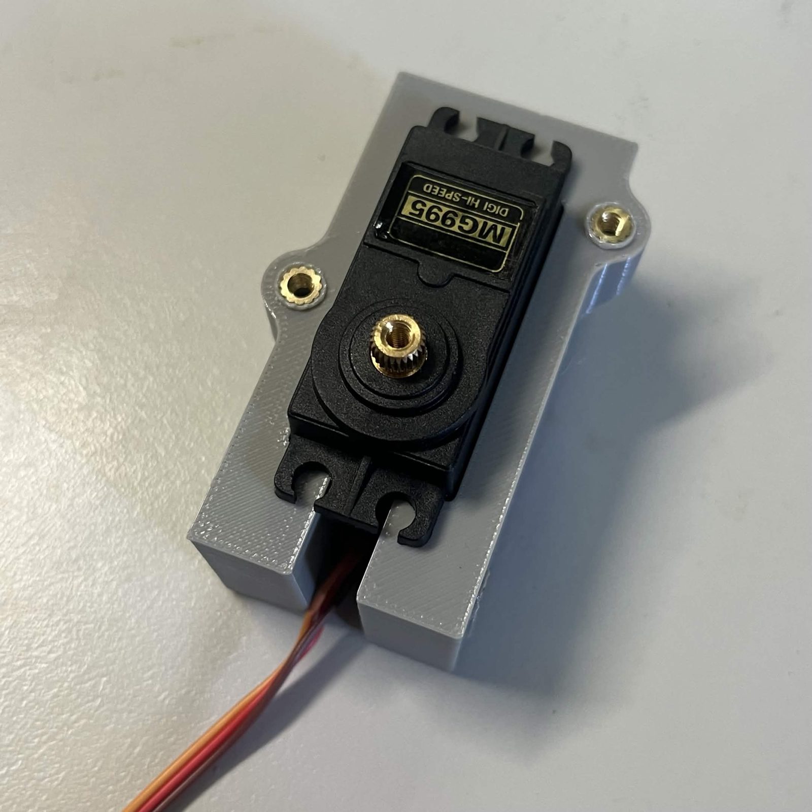
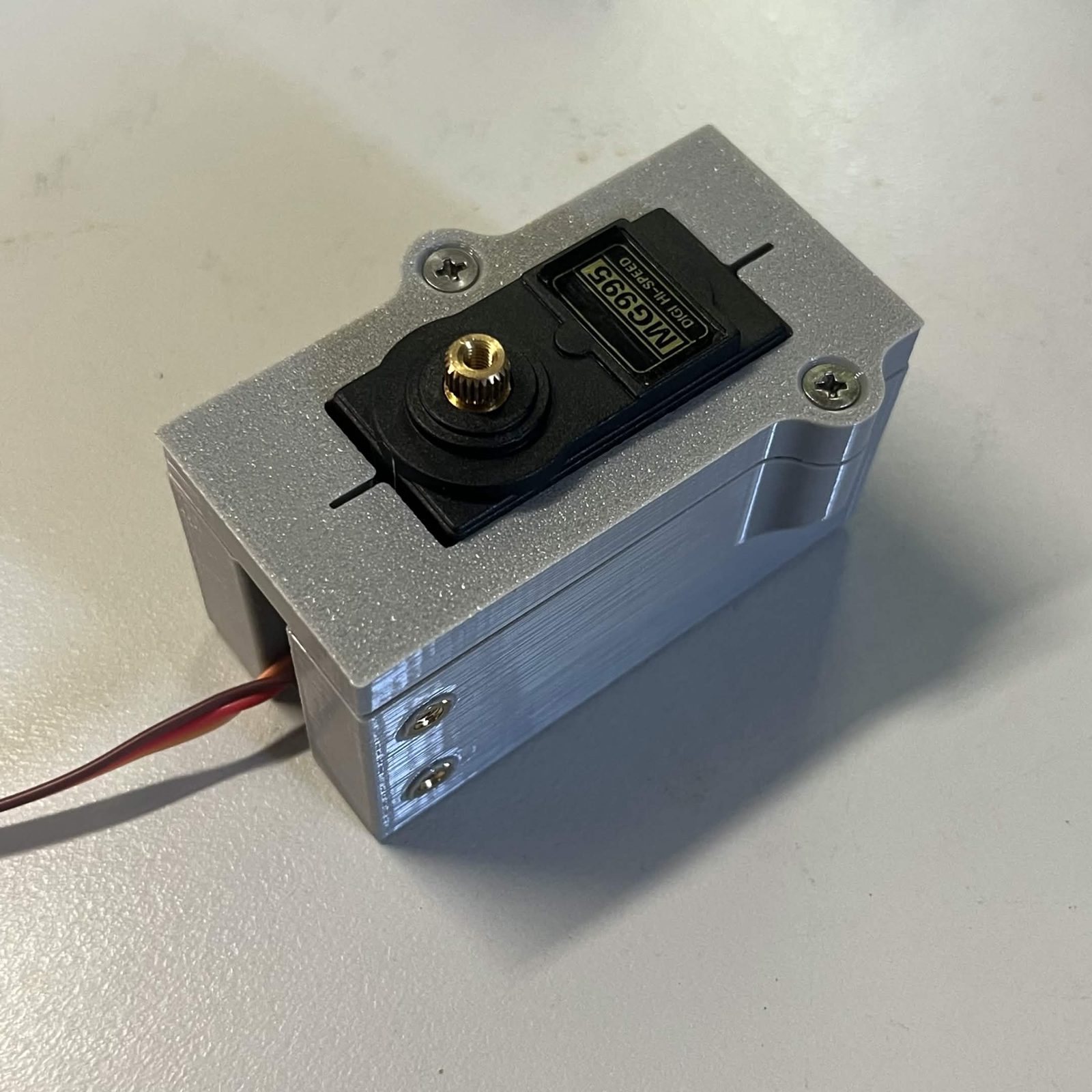
The servo is not screwed down. Slide the MG995 into the housing's pocket, then lay the cover over the open face and drive its 2 M3 × 12 mm countersunk screws into the housing's inserts. Tightening those two is what holds the servo: the cover traps the servo's mounting tabs between itself and the housing.
Use the 12 mm here, not the 8 mm. Snug both down evenly rather than pulling one home first, so the cover seats flat on the tabs.
Step 3 Add the bracket arms
The two arms land on two other faces of the housing. They do not take the same screw, so tell them apart before you pick one up.
- The side arm is the flat slab that covers the whole side of the housing. Its screws finish flush with the face.
- The lower arm is the narrower one that goes under the housing and tapers into a raised end. Its screws finish at the bottom of a deep round well.
Side arm: 2 M3 × 12 mm countersunk into the housing's inserts. Use the 12 mm on this arm.
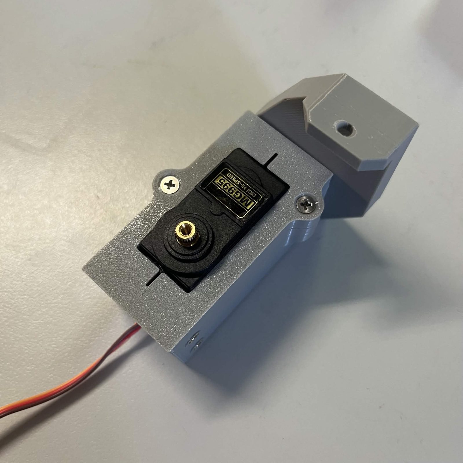
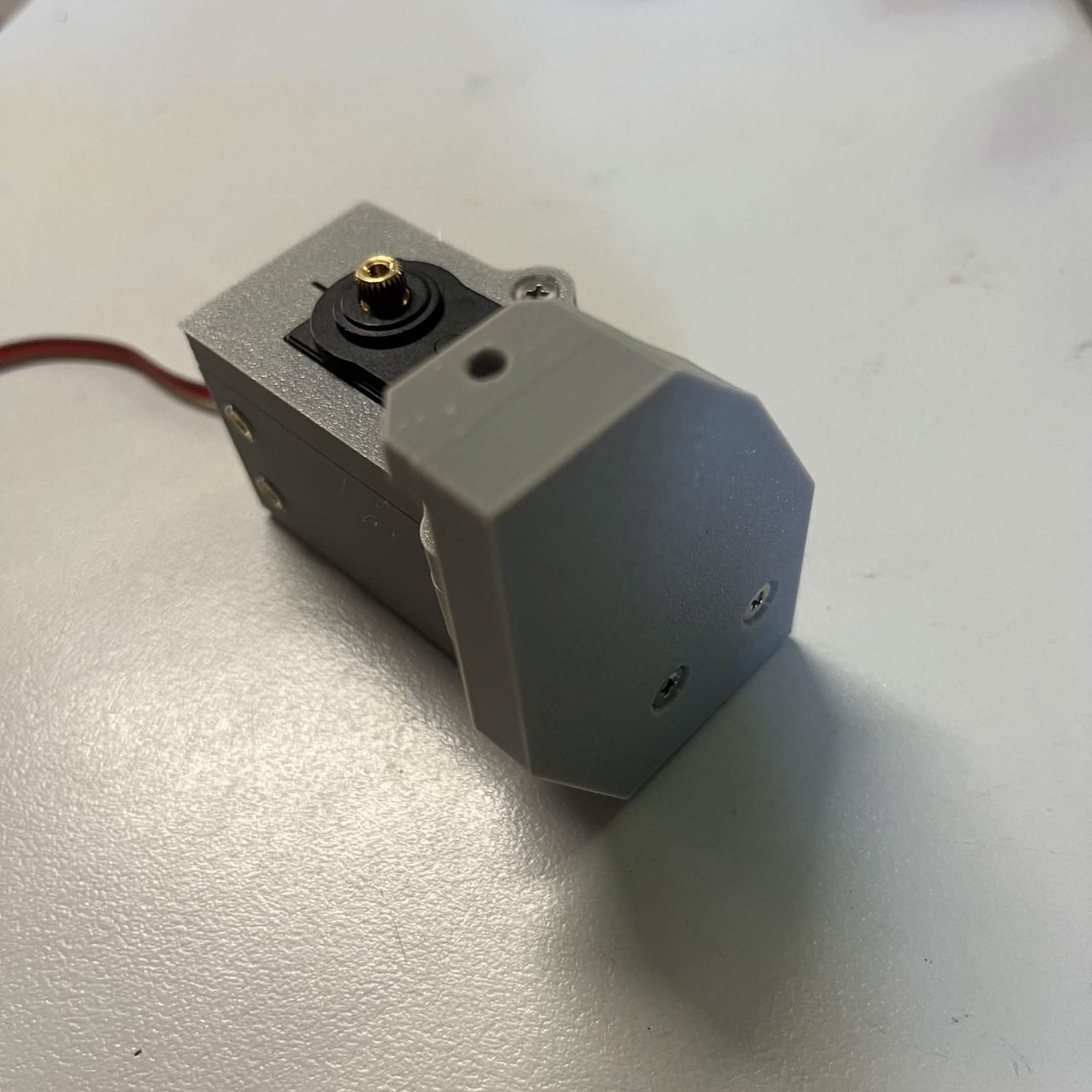
Lower arm: 2 M3 × 8 mm countersunk into the housing's inserts. Use the 8 mm on this arm.
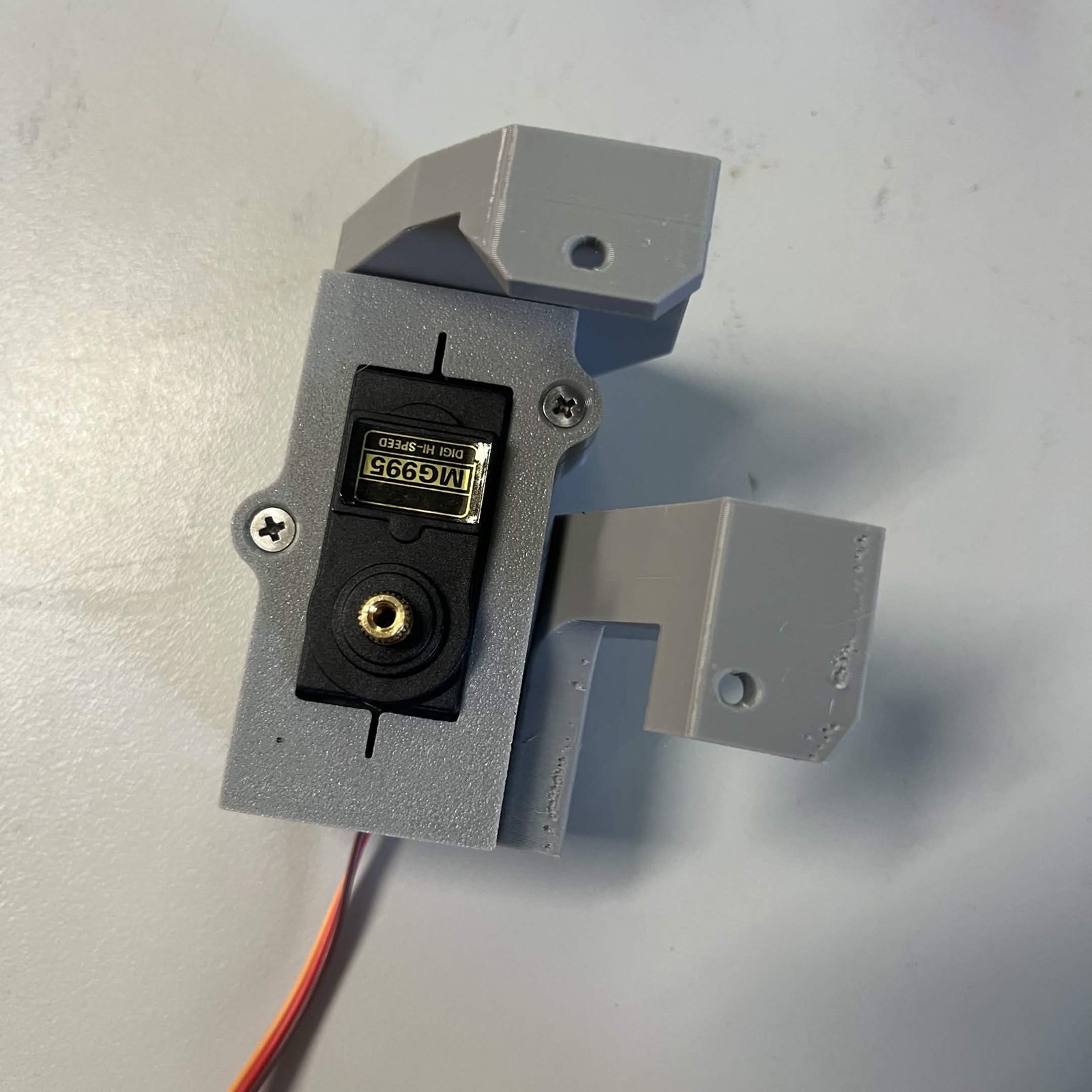
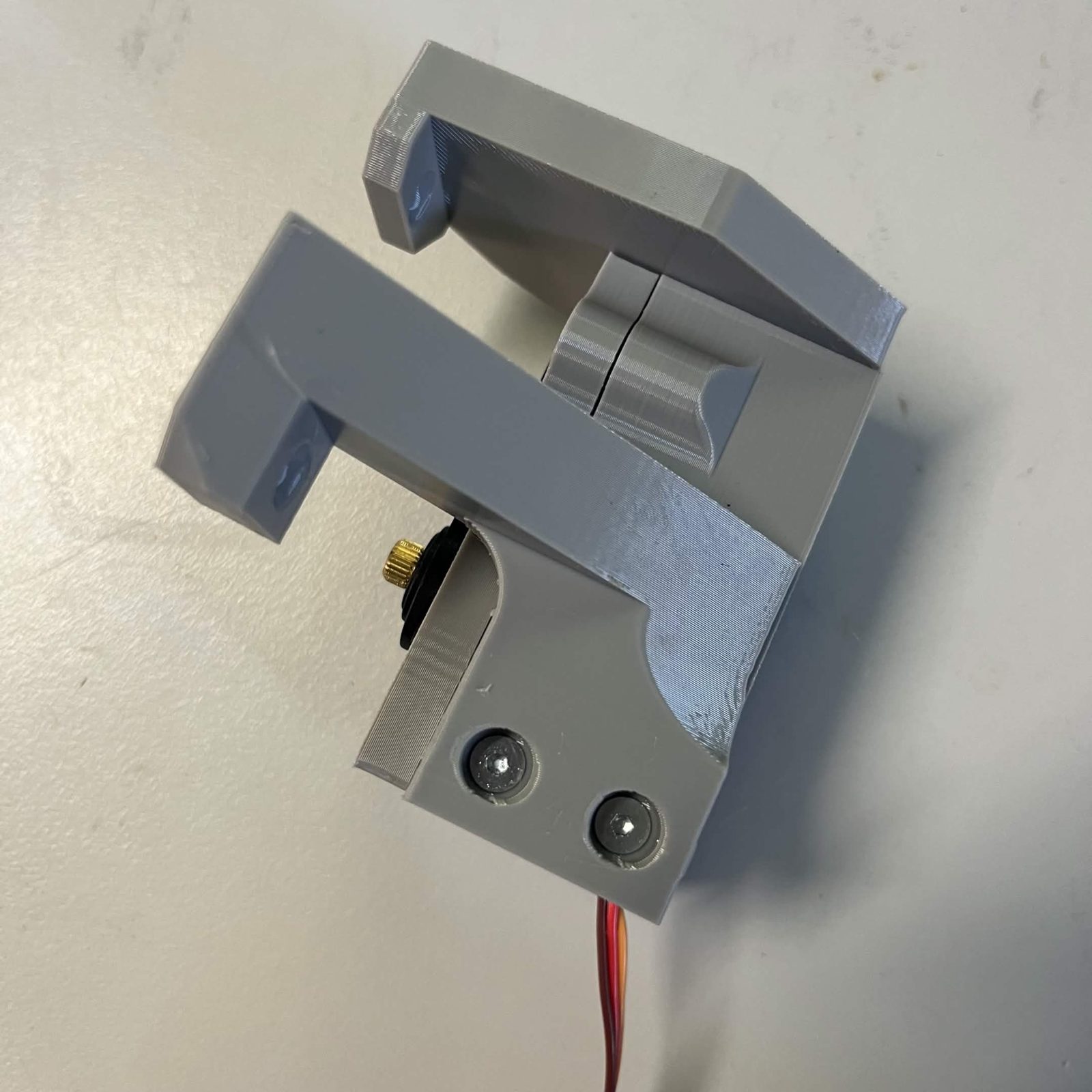
Each arm has one further hole, in the ear at its far end. Those two are not driven here; they are what bolts the finished bracket to the chute core in step 8, so leave them empty.
Step 4 Hang the door on its bearings and the race
The shaft is captured at both ends once this is together, so there is only one order it goes in: the holders have to go onto the shaft before anything is bolted down.
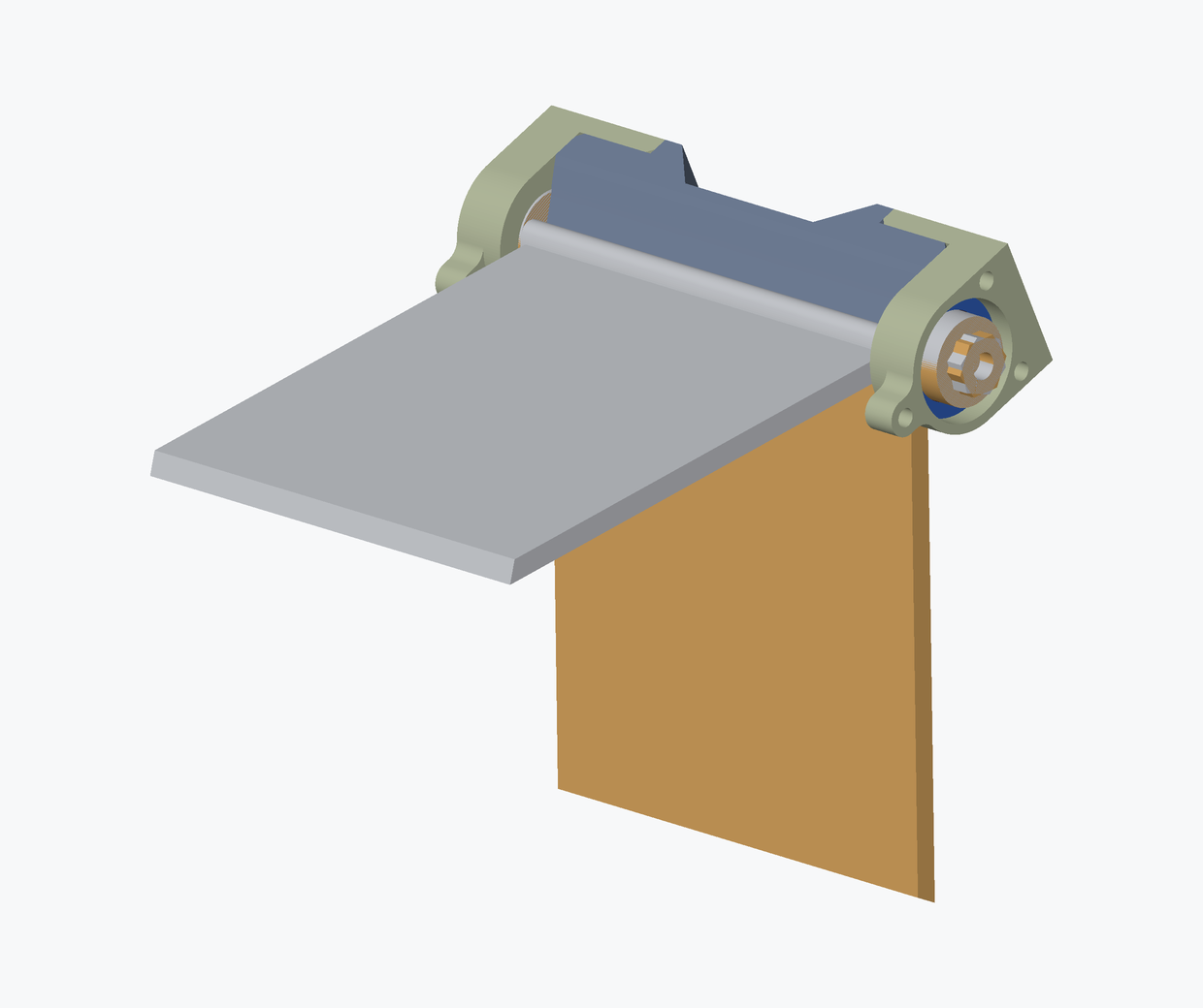
Check which way round the door goes first. The shaft runs the length of the door's top edge, and one end finishes in a hexagonal spigot. That hex end is the servo side: it is what the servo adapter's flap-side half slides onto in step 8. The other end is plain round.
Check the race is the right way round before any of this is bolted up. The shaft sits high on the door's axis and the race's step tucks down and under it, so laid together correctly the race and the door read as one flat plane. If they look like a flight of stairs, the race is round the wrong way. Getting it wrong is a lot of screws to undo. Tip: BrickCycleAlice.
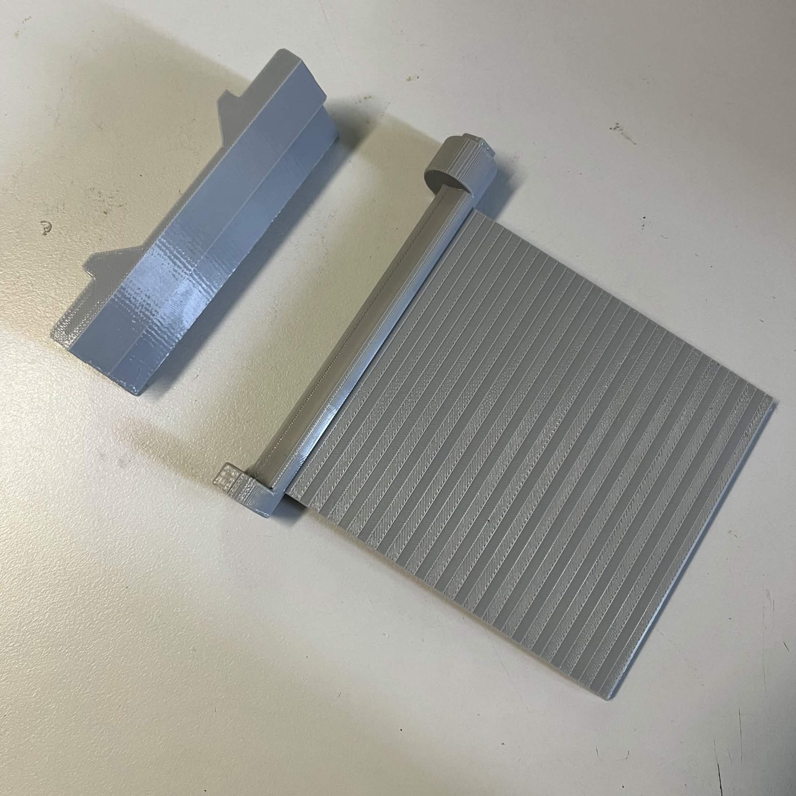
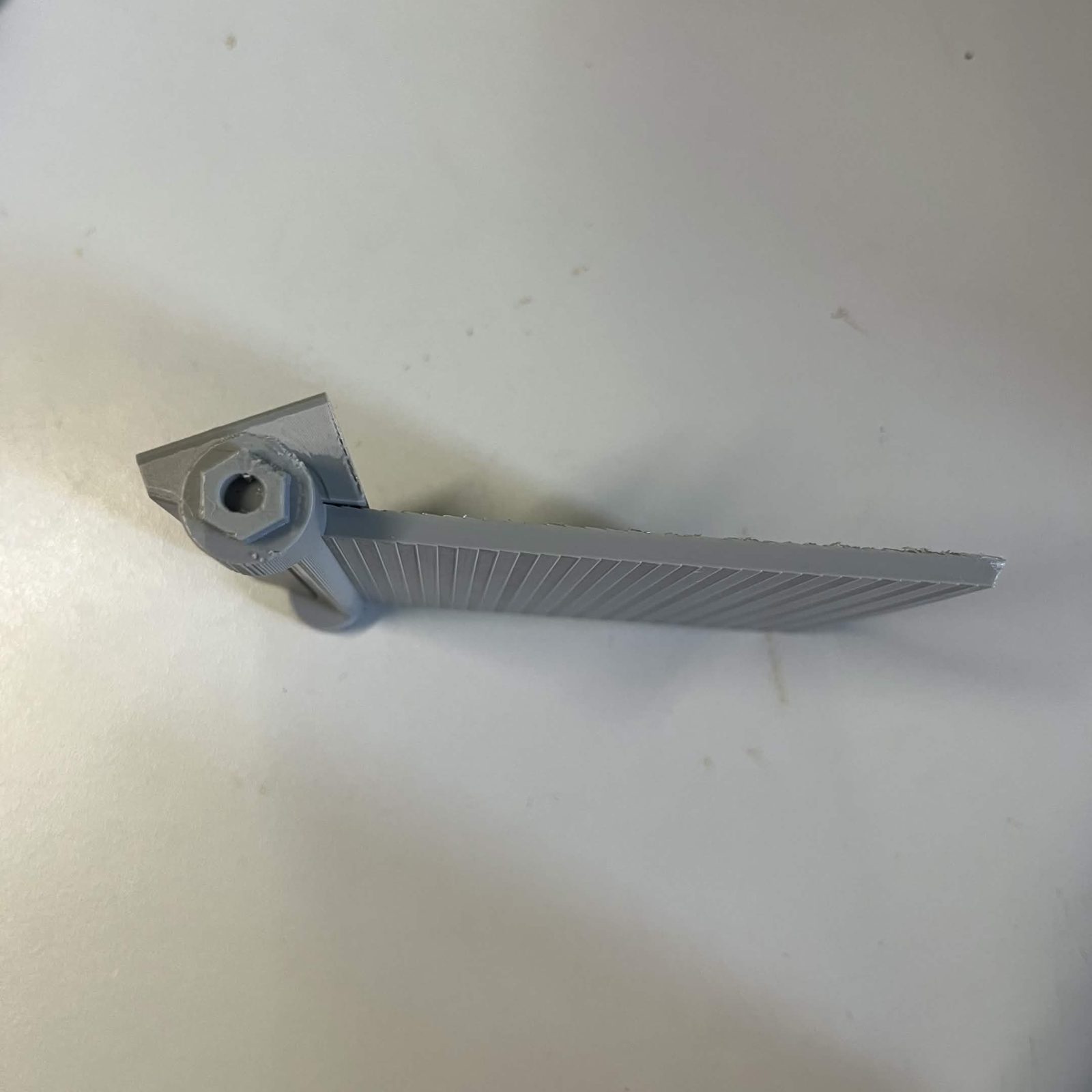
- Slide a holder onto each end of the shaft, bearings already seated. Neither should need forcing.
- Lay the race along the back of the shaft, on the opposite side from the flap, and bolt each holder down onto its end of it: 2 M3 × 8 mm countersunk per holder, 4 in total, into the race's four inserts. The holder seats flat against the race's end. The race arches over the shaft and never touches it; if it does touch, something is not seated.
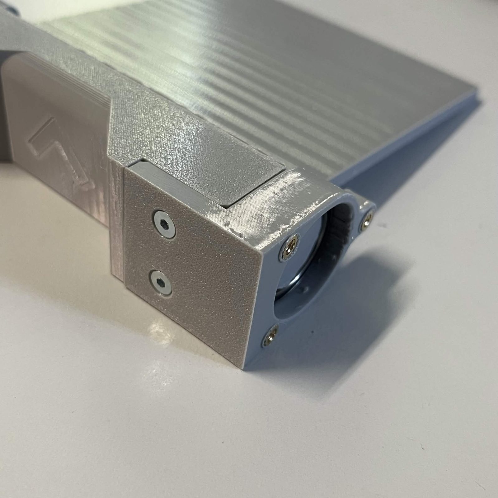
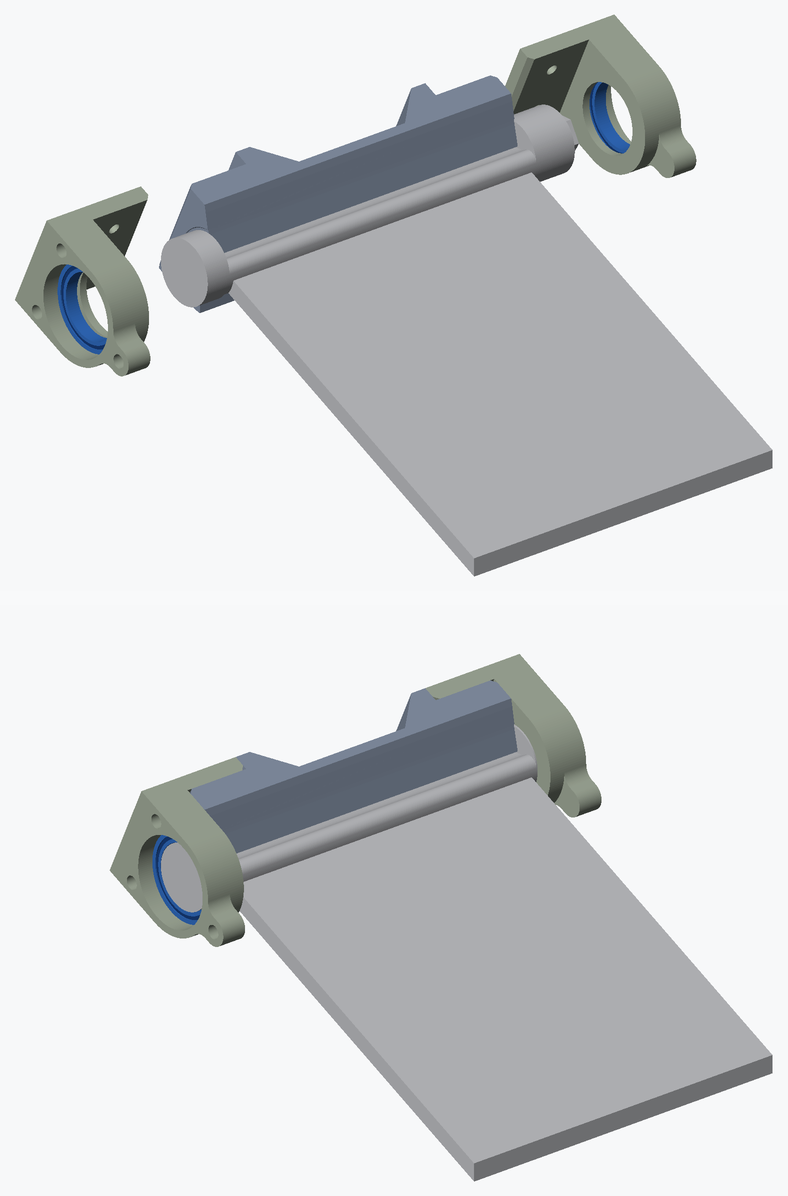
Hung this way the door swings between the two positions below, and it stops against the race at both ends.
Step 5 Fit the bearing covers
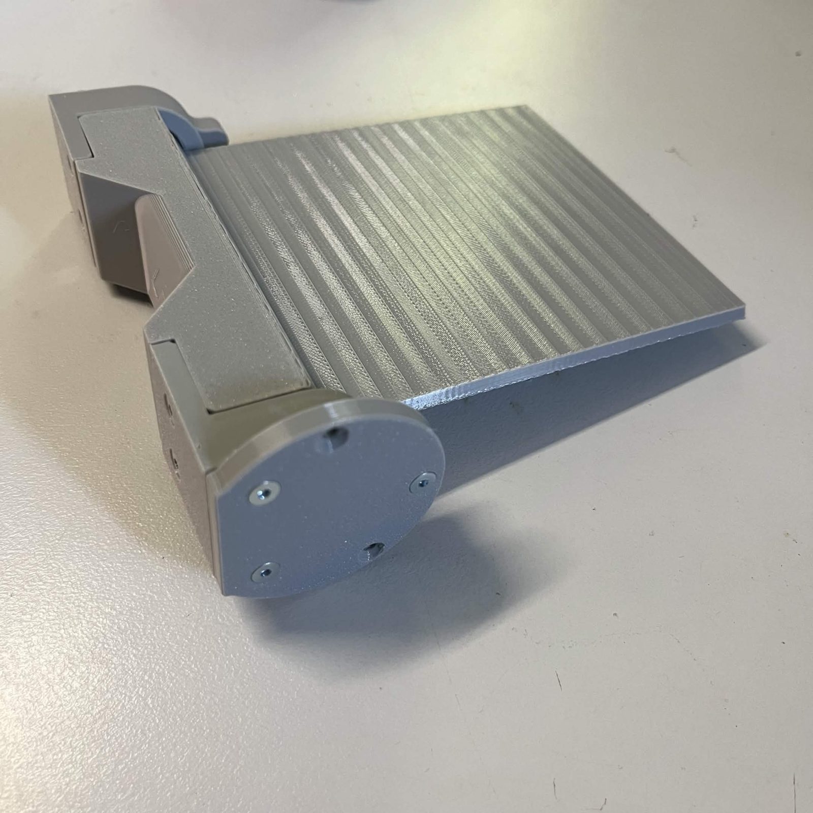
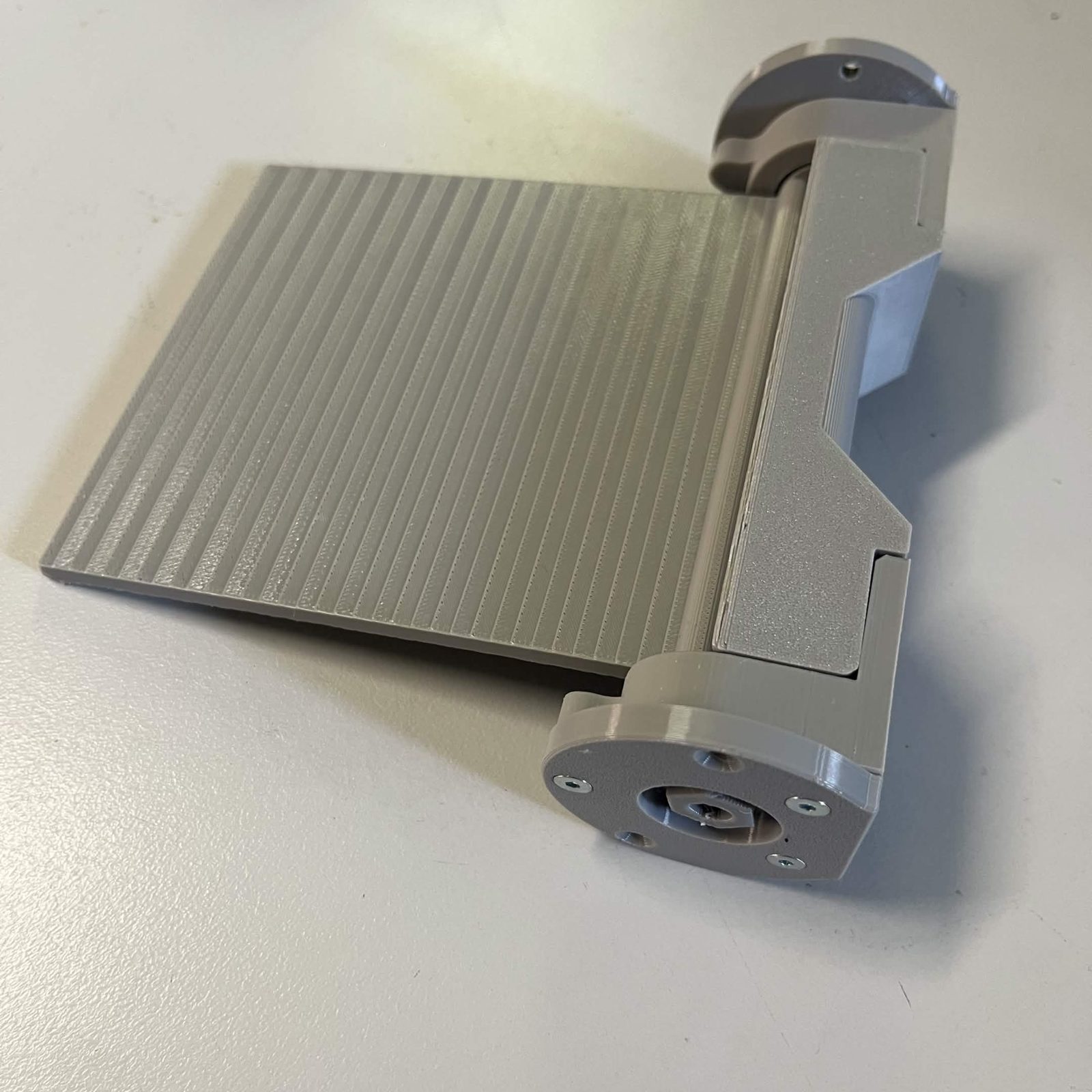
The two covers are not the same part. The Bearing cover (servo) has an open centre and goes on the hex end of the shaft. The Bearing cover (covered) is closed and goes on the plain end.
Put one on each holder with 3 M3 × 8 mm countersunk each, 6 in total, into the three inserts pressed in step 1. The cover's raised rim drops into the pocket on top of the bearing and clamps it against the step: if a bearing has not gone fully home against its lip, its cover will not pull flat. The covers are thin at the rim, so snug the three screws down evenly rather than tightening one fully first.
Each cover has two further holes that stay empty here — they take the screws that hold the flap assembly to the chute core in step 6.
Step 6 Bolt the flap assembly to the chute core
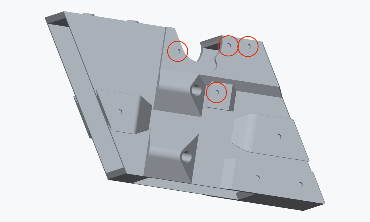
Six of the core's 18 inserts belong to this module. Four are used here, two in step 8:
- 2 bearing covers, 4 M3 × 8 mm countersunk in total, 2 per cover. These are the two holes left empty in each cover in step 5.
- Servo bracket lower arm, 1 M3 × 12 mm countersunk , and side arm, 1 M3 × 8 mm countersunk — step 8.
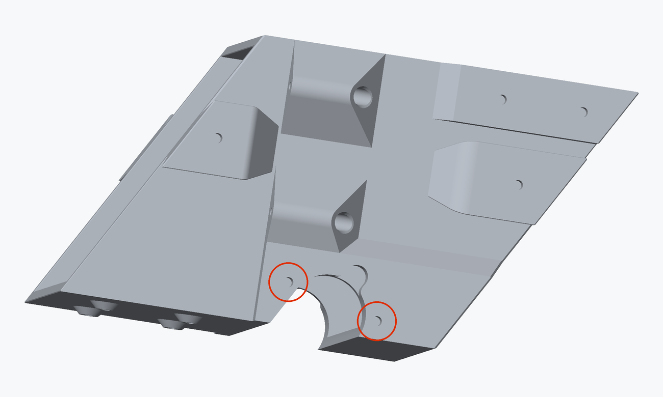
The covers are what hold the flap on. Nothing else in the bearing assembly touches the core: the race and the holders are carried by the two covers, which are already screwed to the holders from step 5. Offer the whole assembly up so a cover lands on each long side of the core, and drive 2 screws per cover into the inserts above.
Snug all four down before tightening any of them, then cycle the door by hand through its full swing. It should turn freely on the bearings and not touch the core anywhere; if it binds, slacken off and let the assembly settle square before tightening again.
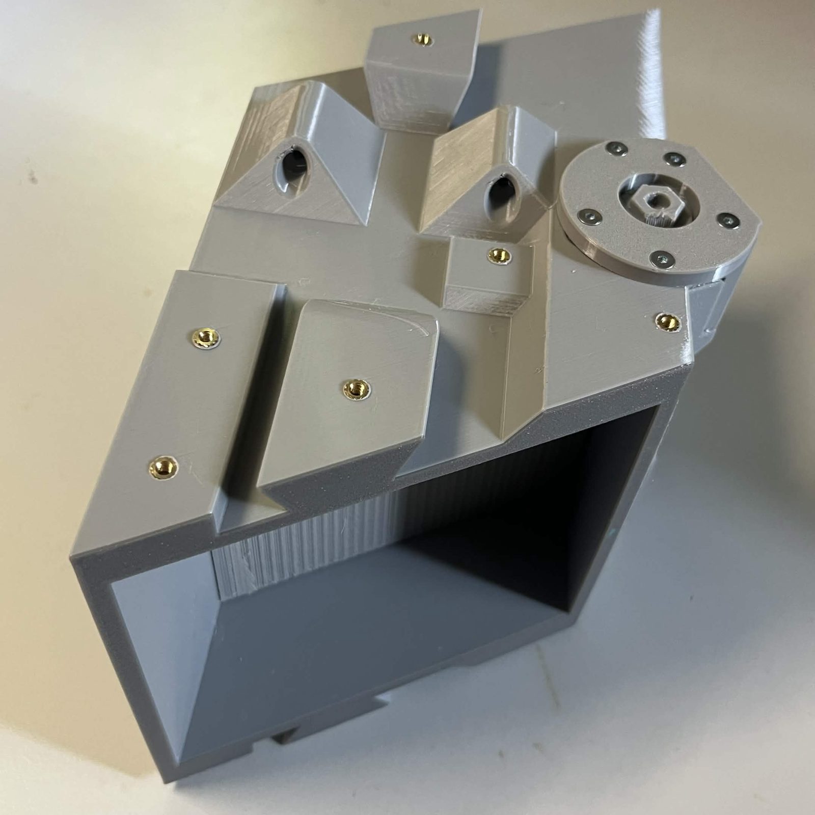
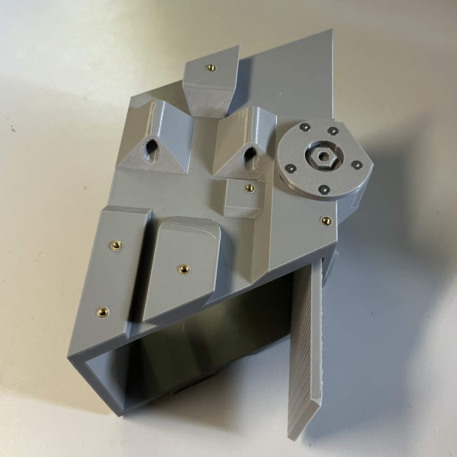
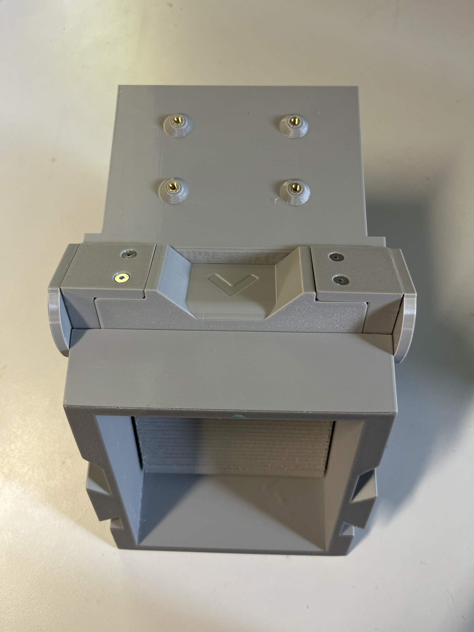
Step 7 Build the servo adapter
The servo-side and flap-side plates clamp the MG995 Servo Horn between them. The horn ships with the servo, it isn't printed. Drop the horn into the servo-side half splined sleeve first: the sleeve sits in the hole in the middle of that half and the two arms lie in the slot around it. It does not fit any other way. Bring the flap-side half down over it and drive 4 M3 × 8 mm countersunk screws through the flap side (it's the half with the visible screw holes) into the servo side. The screws cut their own thread in the printed plastic.
The four screw holes are not spaced evenly around the centre, so the flap side only drops on in two of the four quarter turns. Line all four holes up by eye before you press the halves together, rather than finding out on the third screw. Tip: BrickCycleAlice.
Step 8 Bolt the servo bracket on and couple it to the door
Watch the video below before you finish this step. It is possible to break a door here. See how the coupling is set in the video before you commit to a position. Tip: BrickCycleAlice.
The bracket goes on the same long side as the servo-side bearing cover, into the other two inserts in the first render above. The two arms do not take the same screw here either:
- Lower arm, 1 M3 × 12 mm countersunk .
- Side arm, 1 M3 × 8 mm countersunk .
Then couple the servo to the door through the two-piece adapter you built in the step above. Its servo side goes onto the servo's splined output, through the horn clasped inside it, and its flap side has a hexagonal socket that takes the hex end of the door's shaft, the end step 4 told you to point at the servo. It is a slip fit, so it pushes on without force.
Clock it before you commit: centre the servo (or let it settle at its power-on default), fit the adapter at roughly the middle of the door's swing, then fine-tune once you can check both open and closed by eye. The video below shows how it is set.
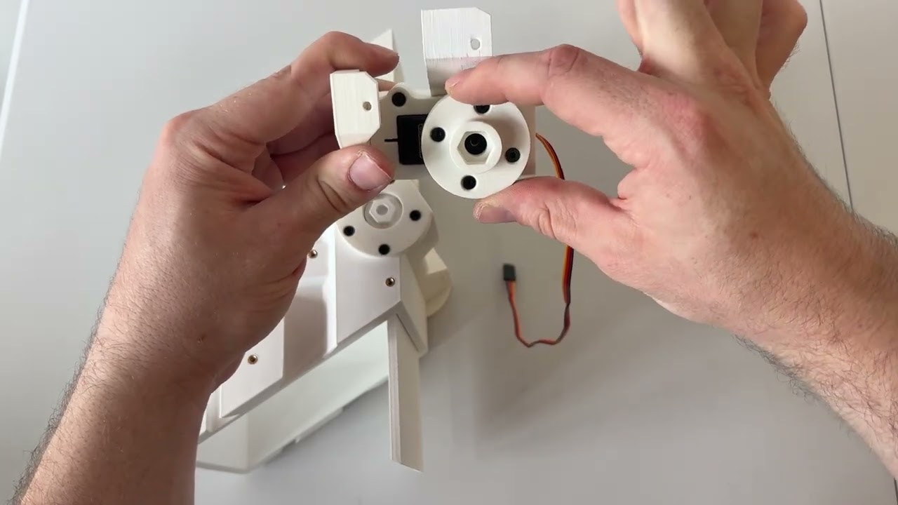
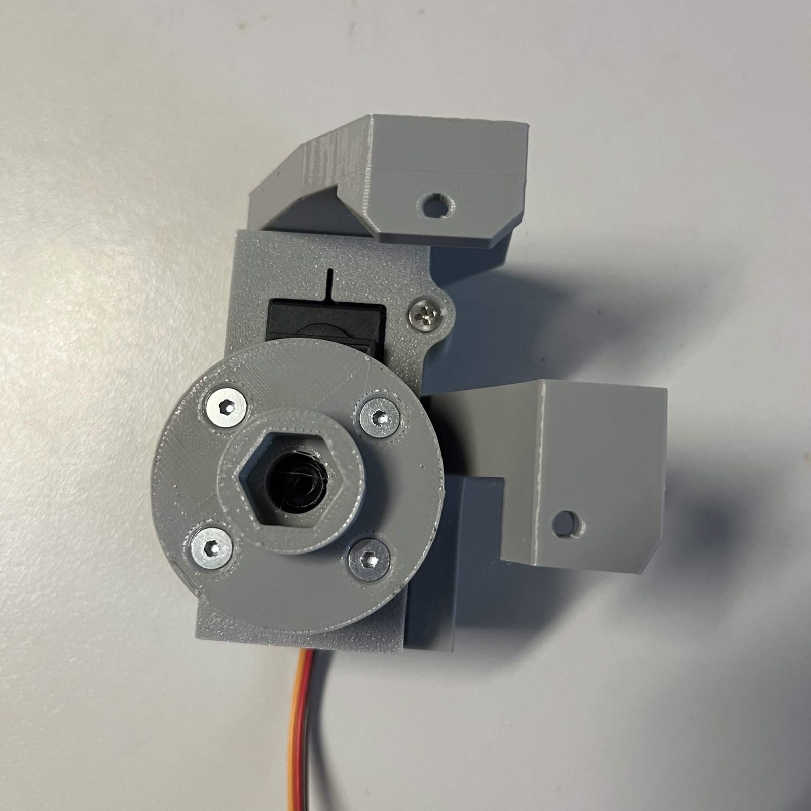
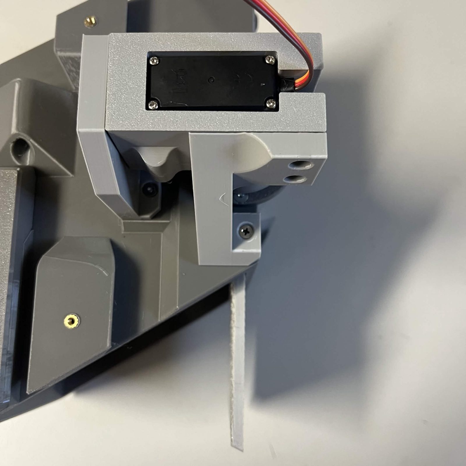
The MG995 only rotates 180°. Install the servo so the door can reach both its fully open and fully closed positions inside that range: clock the horn and set the mounting angle so neither extreme falls outside the servo's travel. Before you tighten anything down, cycle the door by hand through both positions to confirm it swings freely and doesn't bind on the bearings or the core.
The finished result
The module is finished when the bracket is on the core and the adapter couples the servo to the door, and the door swings freely through its whole travel. One of these per layer.
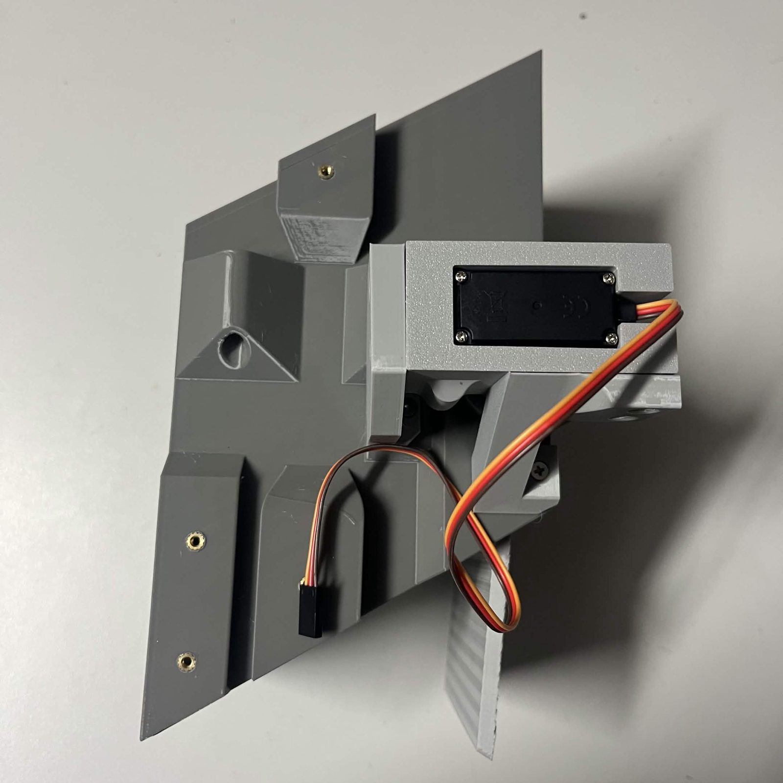
The Chute core page carries the other three sub-assemblies that go on the same core, and is where you should return once you're done here.