
Helpers — Chute limit switch lead (LIM)
Make the chute limit switch lead (LIM)
How-to guideThe lead (LIM) from the control board to the switch that tells the machine where the chute is. Push-on receptacles at the switch, a 3-pin housing with two contacts at the board. One per machine.
The photographs are from a real build; one number is still a guess. Which of the switch's three tabs the two conductors land on is marked as a guess in the harness notes, and no running machine has confirmed it. The build shown below is wired the way this page says. Meter the switch before you crimp.
Parts needed
Wire harness
- 1×0.76 m a machine: the limit switch cable and, if the converter's wires are short, the Orange Pi lead.
- 1×Position 3 stays empty and goes over the pin marked 3.3V.
- 4×Two on the cable and two spares. Pushes onto the switch tabs, no soldering.
- 4×Two on the cable and two spares. Buy a bag of 100.
- 1×Optional. About 600 mm (24 in) over the pair.
Tools needed
- Side cutters, to cut the wire to length
- A ruler or tape measure, to measure 610 mm (24 in)
- Wire strippers that take 22 AWG (0.33 mm²) wire
- Insulated-terminal crimping pliers with a die marked for 22 to 18 AWG (0.33 to 0.82 mm²), for the two #187 receptacles
- Crimping pliers for open-barrel contacts, with a die for 22 AWG (0.33 mm²) wire, for the two Dupont contacts
- Multimeter, to check the finished lead and the switch
- Optional, for the sleeving: scissors and tape, or a hot knife
This is the chute limit switch lead (LIM) on the harness drawings. It runs from J5 on the control board to the roller-lever switch on the chute. One per machine.
Nothing on this lead is soldered. The switch end pushes on, and the board end is two crimps into a housing. The parts list has four receptacles and four contacts, two more of each than the lead uses: the first crimps on a new part are easy to spoil. General help with crimping is at Crimping connectors.
The two ends
- Board end
- Dupont housing, 1x3 female, 2.54 mm (0.1 in), with a contact in two of its three positions. The empty position goes over the pin the board prints
3.3V. - Switch end
- Two #187 insulated quick-connect receptacles, for a 4.75 x 0.5 mm (0.187 x 0.02 in) blade. They push straight onto the switch's tabs.
- Wire
- 22 AWG (0.33 mm²), two conductor. Cut it 610 mm (24 in) long. Use black for the ground wire and white for the signal wire.
LIM) end to end. The empty third position goes over the board's 3.3 V pin.#187 is the small one. The far more common #250 receptacle is 6.35 mm (0.25 in) wide and will not grip these tabs. Check the size on the packet, not the picture.
The connections
Three positions on the housing, three tabs on the switch. Two wires join them:
- Wire 1
- Housing position 1, which is ground, to
COMorNCon the switch. - Wire 2
- Housing position 2, which is the signal, to the other of
COMandNC. - Position 3
- Nothing. It stays empty and sits over the board's 3.3 V pin.
NO- Nothing. This tab on the switch stays bare.
Which wire goes to COM and which to NC does not matter. The switch only closes the circuit between the two, so the two wires can swap ends. What does matter is that one wire is in position 1 and the other in position 2.
The switch prints its own tab names. The body carries a little schematic with NC and NO against the two tabs on its side and COM against the one on its bottom edge, so you can read the three off the switch in your hand rather than counting positions.
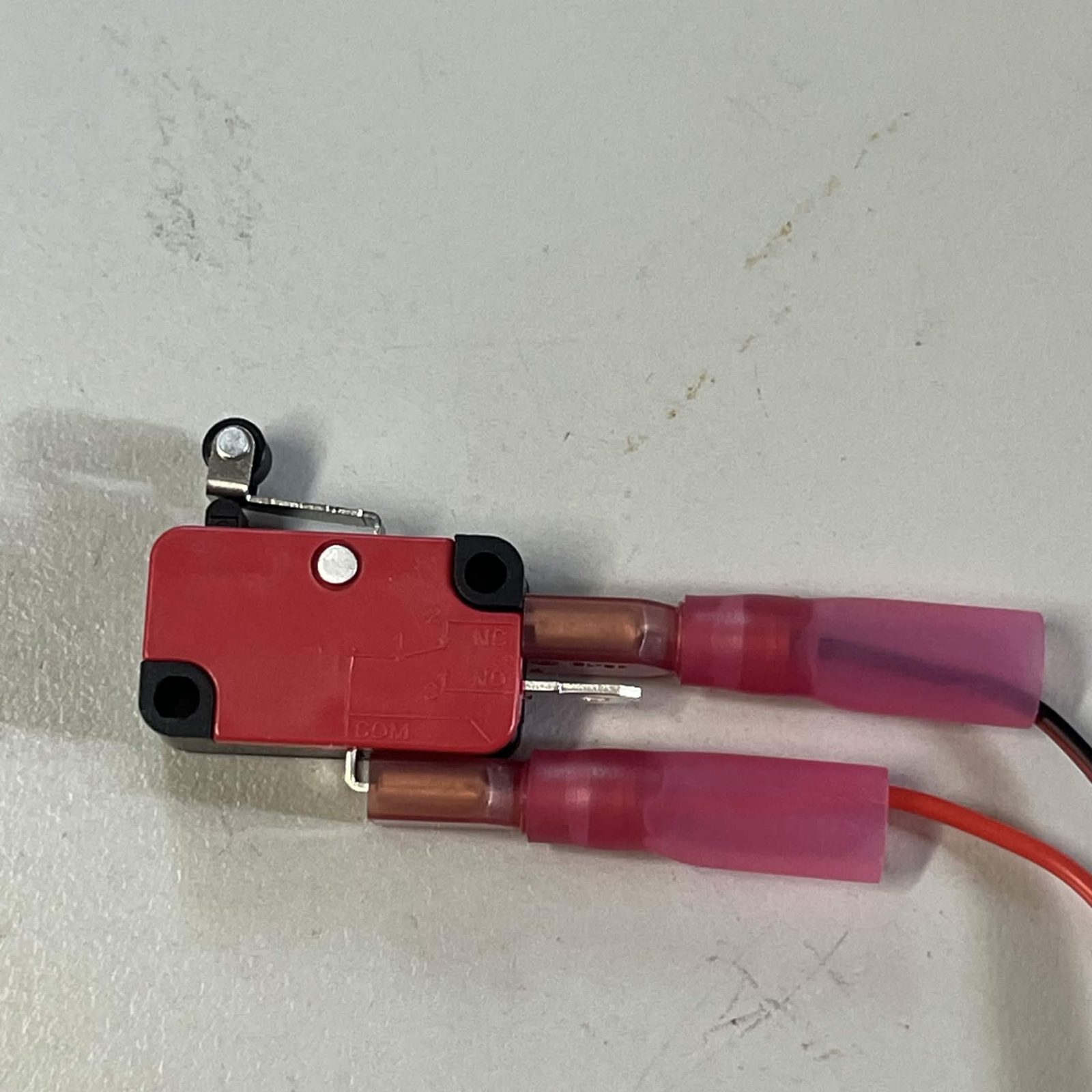
COM and NC. The bare blade between them is NO, which stays empty. Photo: BrickCycleAlice.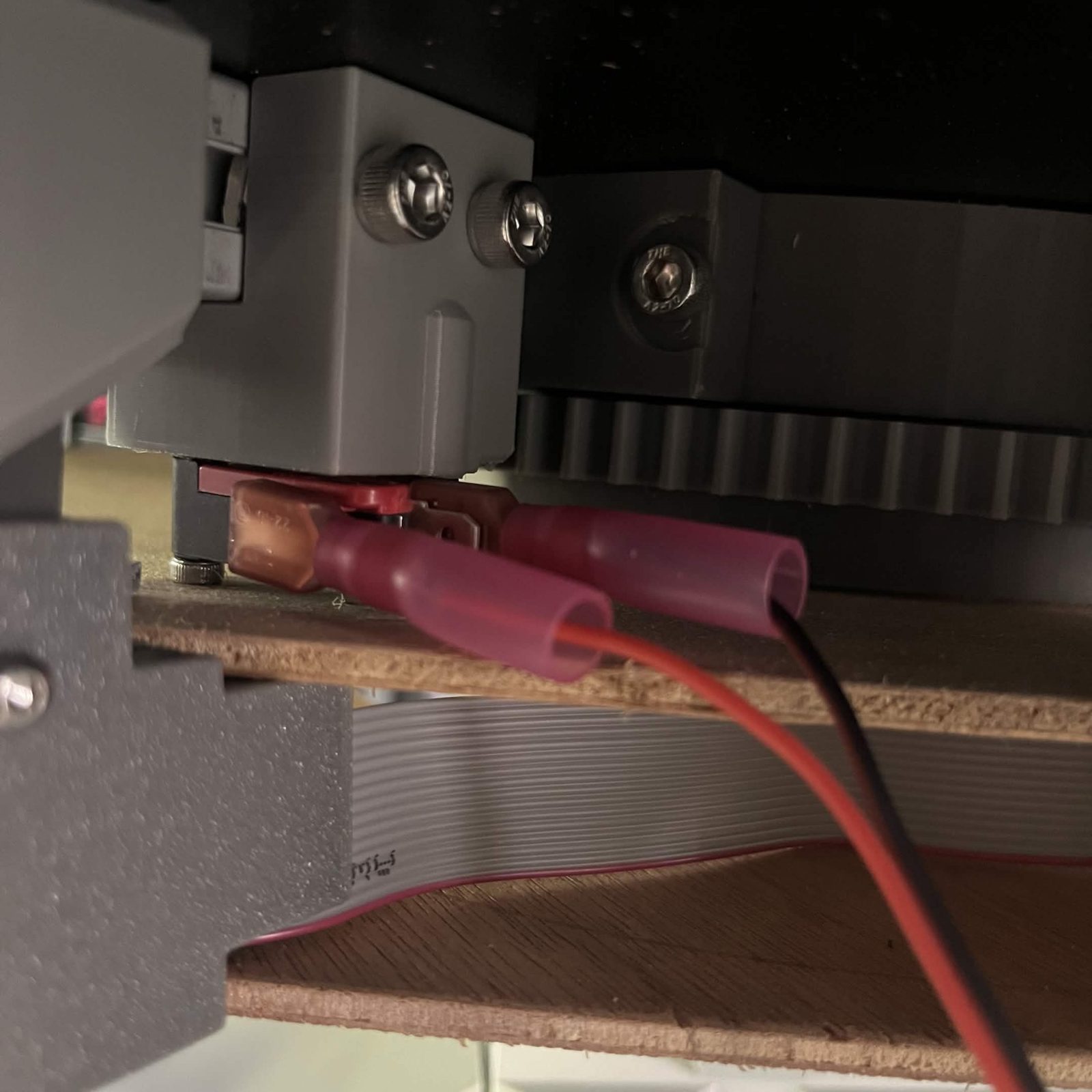
The switch is an SPDT with three tabs and the third one, NO, stays bare. Wired to COM and NC the circuit is closed while the lever is free and opens when the chute presses it, which is the way round the machine expects. If homing later runs the wrong way, that is a setting in the software rather than a rewire.
The choice of tabs is unverified. The harness notes mark it as a guess and no built machine has confirmed it. Before you crimp, meter the switch: continuity between two tabs with the lever free, and none with the lever pressed, is what confirms the pair the printing names.
Build it
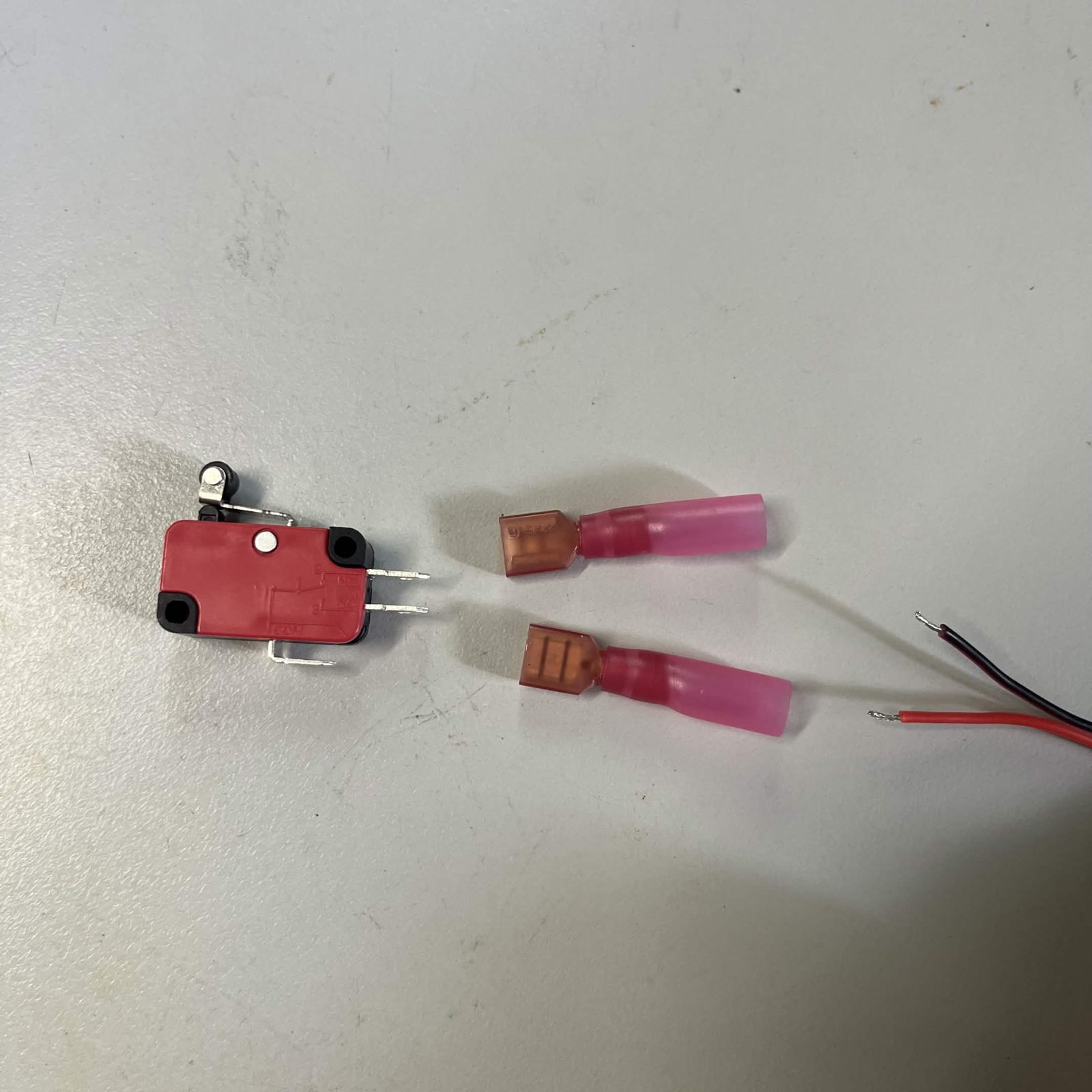
- Cut 610 mm (24 in) of the pair.
- Optional: if you will sleeve the lead, slide a 600 mm (24 in) length of braided sleeving over the pair now, before you crimp anything onto either end. A finished receptacle or housing may not go through it, so it goes on first. Leave it bunched up on the pair for now; Sleeving (optional) says how to cut and finish it.
- At the switch end, crimp a #187 receptacle onto each of the two conductors, as under Crimping a #187 receptacle, below.
- At the board end, crimp a Dupont contact onto each of the two conductors, as under Crimping a Dupont contact, below.
- Push the two contacts into the housing from the back until each one clicks: the black wire into position 1, the cavity next to the moulded arrow, and the white wire into position 2. Position 3 stays empty.
- Check the lead, as under Check the lead, below.
- Push the two receptacles onto
COMandNC. They are a firm push; the switch does not need holding in anything to do it.
Crimping a #187 receptacle
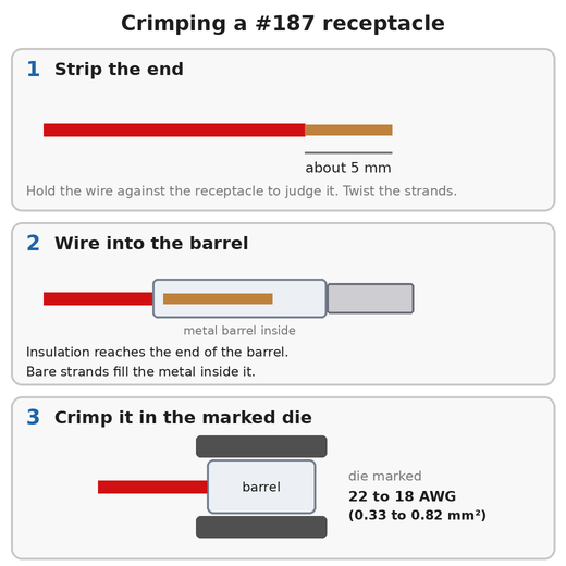
A #187 receptacle is a metal barrel inside a plastic sleeve. It takes 22 to 18 AWG (0.33 to 0.82 mm²) wire, so your 22 AWG (0.33 mm²) wire is at the thin end.
- Strip about 5 mm (0.2 in) off the end. Hold the wire against the receptacle to judge it: the bare strands should fill the metal barrel, and the insulation should reach the end of the barrel.
- Twist the strands tight and push them into the barrel as far as they go.
- Close the barrel in the die of the insulated-terminal pliers marked for 22 to 18 AWG (0.33 to 0.82 mm²), with the metal part in the die. Choose the die by the size marked on it, not by the colour of the sleeve.
- Pull on the wire to check it holds. Do the same on the other conductor.
#187 is the small one. The far more common #250 receptacle is 6.35 mm (0.25 in) wide and will not grip these tabs. Check the size on the packet, not the picture.
This is not the die for the Dupont contacts. Pliers made for open-barrel contacts do not close an insulated receptacle properly. The Dupont contacts take their own die, below.
Crimping a Dupont contact
A Dupont contact takes 22 to 28 AWG (0.08 to 0.33 mm²) wire, so your 22 AWG (0.33 mm²) wire is at the thick end of what it takes.
- Strip about 2 mm (0.08 in) off the end and twist the strands tight.
- Close the contact's inner wings on the bare strands and its outer wings on the insulation, in the die of the crimping pliers marked for 22 AWG (0.33 mm²) wire. No strands should stick out past the inner wings.
- Pull on the wire to check it holds, then push the contact into the housing from the back until it clicks.
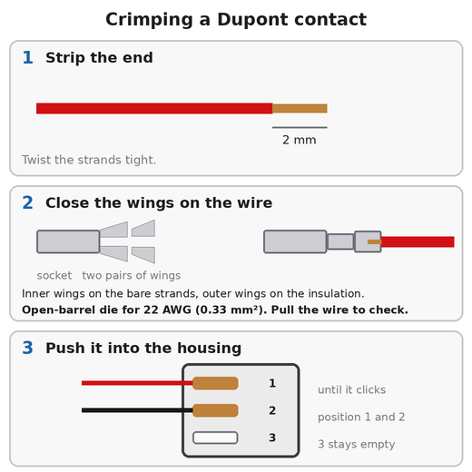
Choose the die by the size marked on it, not by its colour.
Check the lead
Do this before the receptacles go on the switch. Set the multimeter to continuity.
- Touch one probe to the contact in position 1 and the other to one of the two receptacles. It beeps for one of them. That receptacle is wire 1.
- Touch the probe on position 1 to the other receptacle. It does not beep.
- Touch the two contacts in the housing to each other. They do not beep.
If the second test beeps, or the third does, something is shorting: strands are crossing at a crimp. If the first never beeps, a crimp has not gripped.
Then push the receptacles onto the switch and meter the housing again. With the lever free, positions 1 and 2 read continuity. Press the lever and they read open circuit. If it is the other way round, the receptacles are on COM and NO: move one tab along.
Putting the housing on the board
The housing is not keyed, so it can go on J5 either way round. Turned over, the two wires land on the 3.3 V pin and the signal pin: nothing is damaged, but the machine never sees the switch change.
The board prints 3.3V and SIG beside J5. Push the housing on with the empty position over the pin marked 3.3V. Ground is the pin at the other end, on the square pad, and that is where the moulded arrow ends up: the arrow always marks ground.
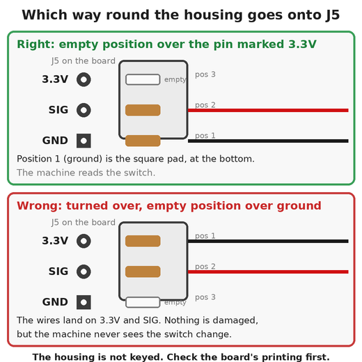
3.3V. The same housing turned over is wrong.Sleeving (optional)
You can skip this and the lead works the same. The sleeving is on the parts list as optional. It keeps the wires together as one tidy cable and protects them where the lead runs along the frame, and it is another way of securing the cables.
Where: over the pair, from just short of the two receptacles to just short of the Dupont housing. About 600 mm (24 in).
How:
- Push the braid together lengthwise to open it: it widens as it shortens. Feed all the wires into it together, so none of them is left outside.
- Cut it to length with a hot knife or a soldering iron with a blade tip, so the cut melts shut. Plain scissors leave the braid fraying. With no hot tool, wrap a turn of tape around the braid where you will cut, cut through the middle of the tape with scissors, and leave the tape on.
- Stop the sleeving 5 to 10 mm (0.2 to 0.4 in) short of the receptacles and short of the housing, so the two receptacles can pull apart to go on their tabs and the sleeving never crowds into the housing.
- Hold each end with a small piece of heat shrink or a turn of tape, so that the braid cannot creep back along the wires.
Leave the sleeving loose enough to bend, and do not tie it down so tightly that it crushes the braid.
The finished result
One lead (LIM), 610 mm (24 in), with a #187 receptacle on each conductor at the switch end and a 3-pin Dupont housing at the board end whose third position is empty.
Where it goes
Onto J5 at connecting the components, step 3. J5 is the header the board prints HALL_SW_0; J6 beside it is a spare input and is not this one.
Reference
The vendor drawing for this lead (LIM), its bill of materials and its downloads are on the WireViz
drawings page. It shows the same lead in the form a cable supplier quotes from.