
Electronics — Control board housing
Control board housing
How-to guideClosing the control board into its printed housing, with the 40 mm fan on a GPIO-controlled port and the reset plunger in its lid.
AI-generated first draft. Steps 1, 2 and 5 are photographed from a build. Nobody has printed the cover, the plunger or the fan retainers yet, so steps 3, 4, 6 and 7 are written from the models, and the pictures in them are renders.
Parts needed
Printed parts
- 1×
- 1×
- 1×
- 1×
- 2×
Electronics
- 1×
Heat inserts
- 8×
Screws
- 4× 6mm
- 4× 12mm
- 6× 8mm
A an interchangeable alternative works (hover for what).
Tools needed
- Hex keys, 2 mm and 2.5 mm
- Soldering iron or heat-set insert press
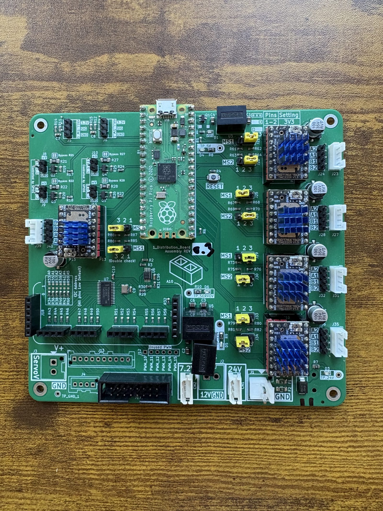
Prepare the control board before you start. The five stepper drivers, the Pico and the ten jumpers all go in while the board is loose. Preparing the control board does that; step 2 here screws the finished board down.
The fasteners and quantities are in the parts list above and are called out inline at each step.
Fastener icons match the parts list: the silhouette is the head shape, the colour is the thread size. M3 M4 M5 M6
Eight screws go into the base: four hold the board down, four close the cover over it.
Step 1 Preparation
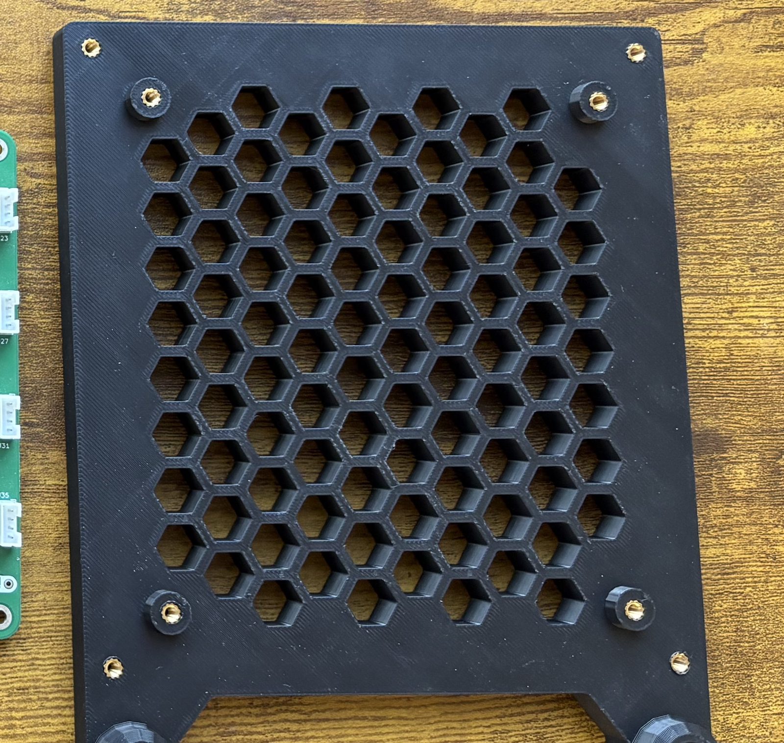
Press 8 M3 inserts into the base while it is loose: four on the inner bosses for the board, four at the corners for the cover. See installing heat inserts. Nothing else takes one.
Control Board Housing base: 8 × M3
Step 2 Screw the board to the base
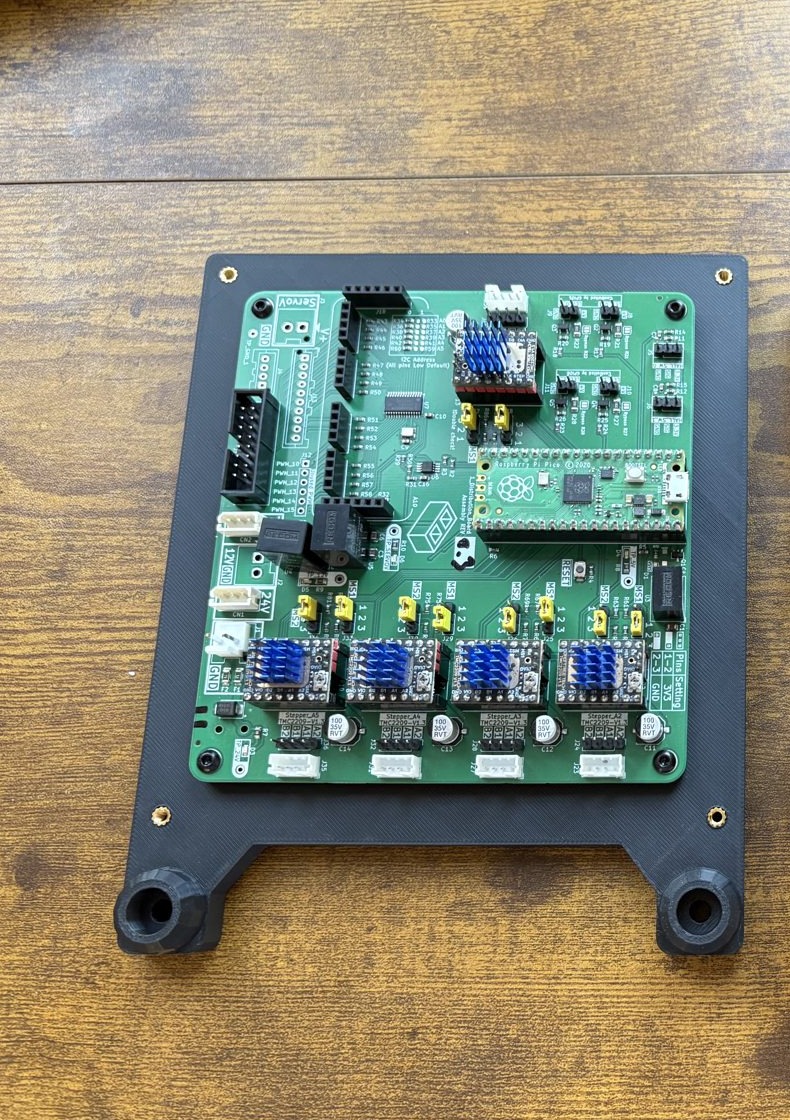
Sit the board on the four inner bosses and fix it with 4 M3 × 6 mm button head screws. No standoffs: the bosses are the standoffs.
Step 3 Fit the fan inside the cover
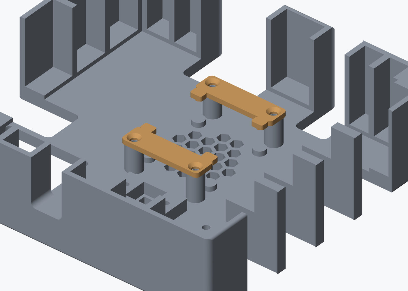
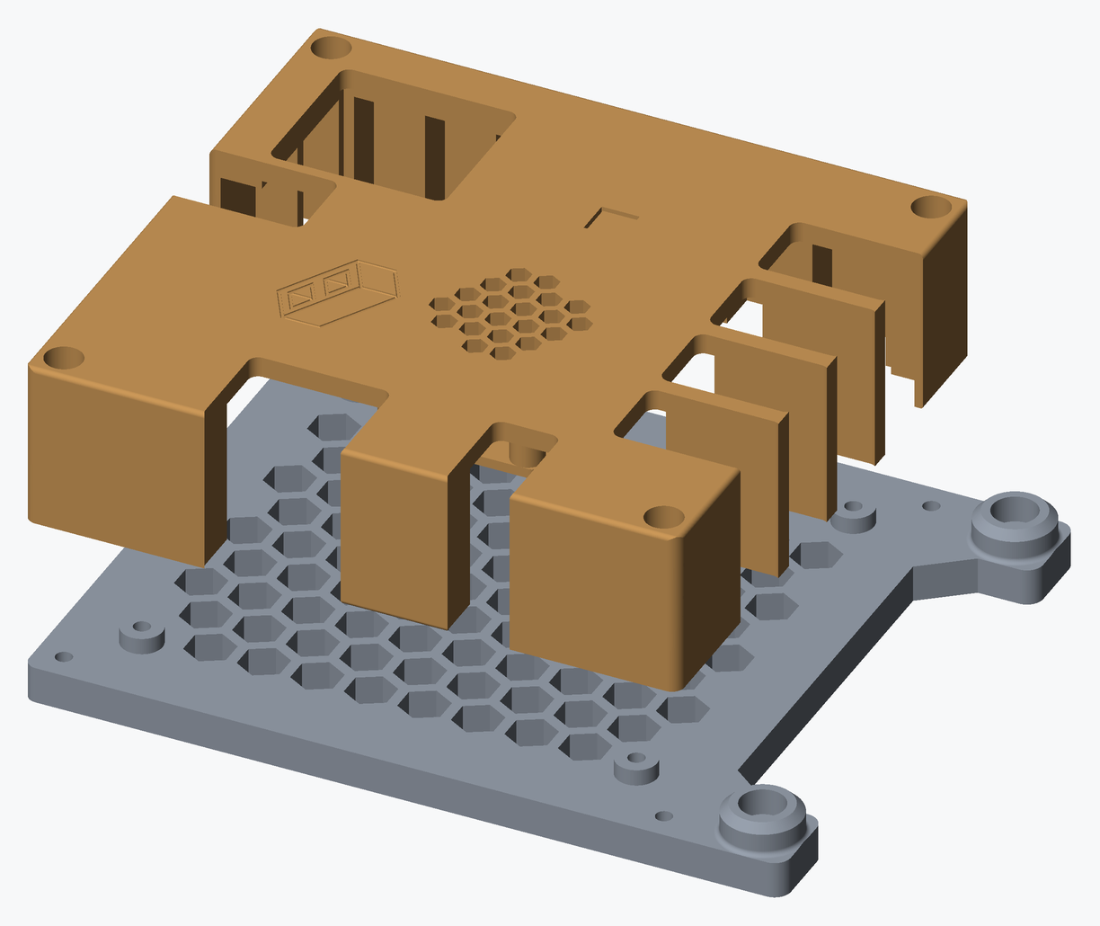
Turn the cover upside down. The fan sits over the honeycomb vent and two printed retainers hold it there, one at each end of the fan.
- Lay the fan over the vent, label facing into the enclosure so it blows inwards.
- Lay a retainer across each end of the fan, pegs down, so its two pegs drop into the fan's corner holes. Each retainer lands on two of the cover's four posts.
- Screw each retainer down into its two posts with 2 M3 × 8 mm countersunk screws. Drive all four by hand and stop as soon as the retainer is flat on its posts: they cut their own thread in the plastic.
- Route the fan's lead to the cutout in the corner of the cover.
Step 4 Fit the plunger and its retainer
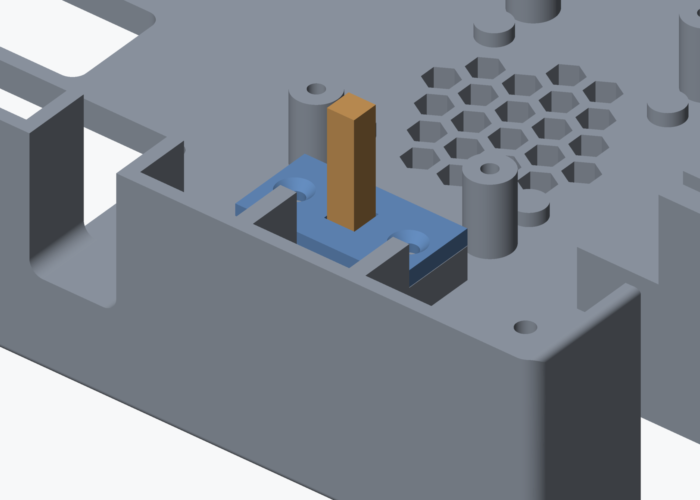
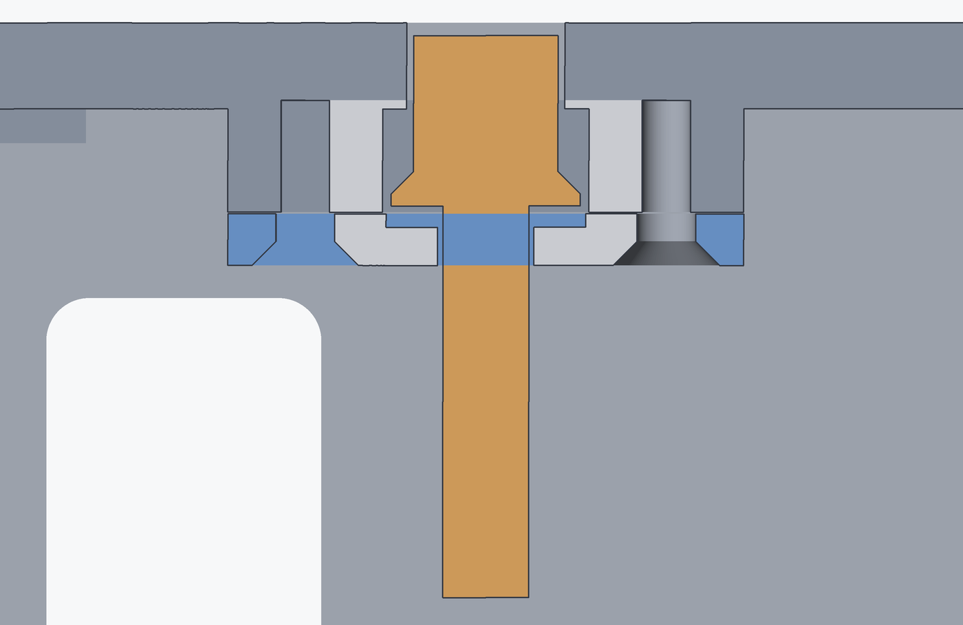
The plunger lands on the board's reset button, so the button can be pressed with the housing shut. Drop it through the slot from the outside of the cover, then hold it in with the retainer on 2 M3 × 8 mm countersunk self-tapping screws. It should slide freely and fall back on its own.
Step 5 Plug the fan into a GPIO-controlled port
The fan runs off one of the board's four LED ports. The red wire goes to +V.
- LED_0_1, LED_0_2
- GPIO1 (output channel 0)
- LED_1_1, LED_1_2
- GPIO6 (output channel 1)
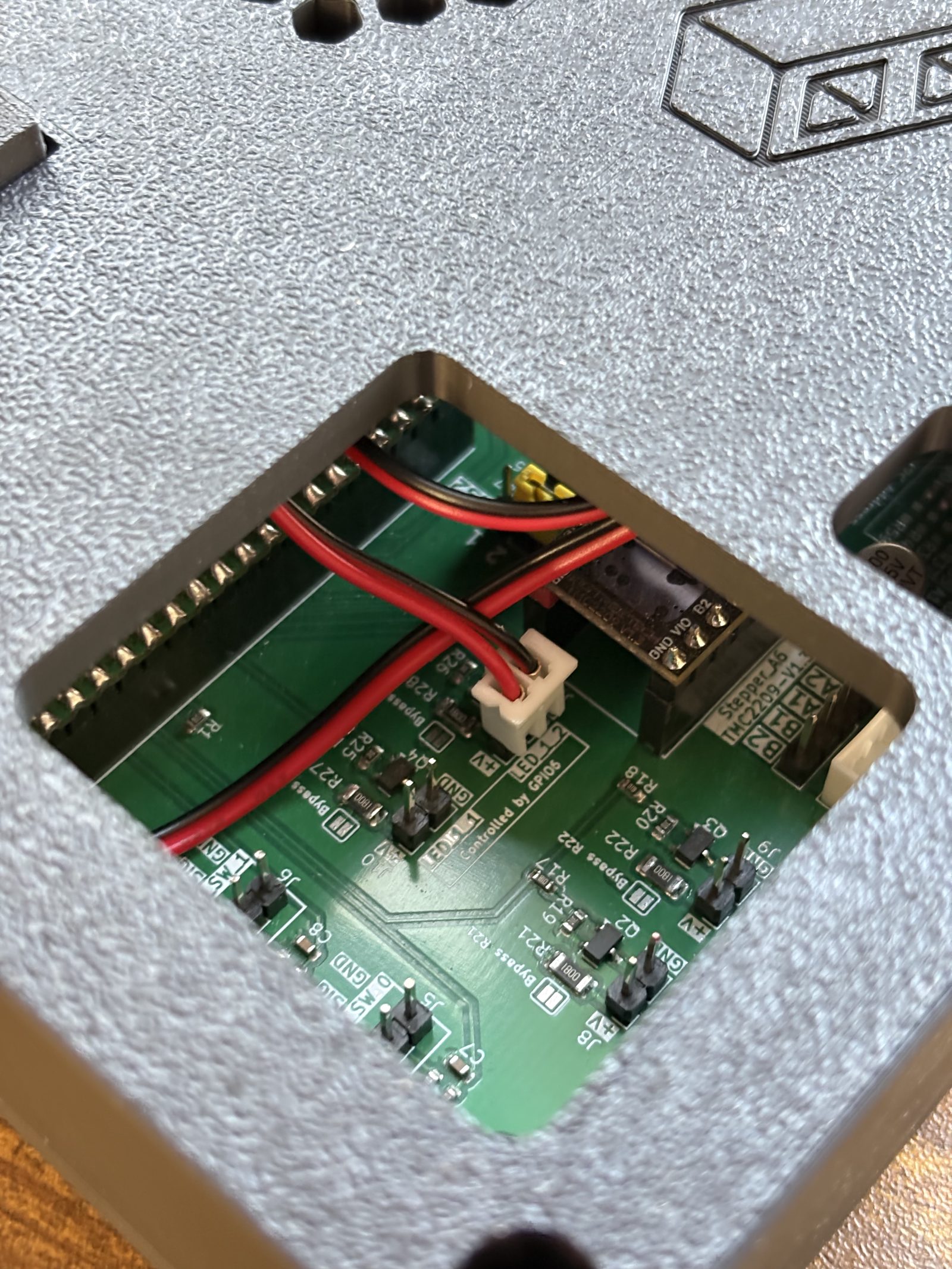
Double check the port's bypass jumper is bridged. Each port feeds +V through a 180 Ω resistor meant for a bare LED board, and with it still in circuit the fan will barely turn, if it turns at all, because most of the 24 V drops across the resistor instead of reaching the fan. All four are bridged in preparing the control board, step 4; look for solder across the two pads marked Bypass R21, R22, R27 or R28 beside the port you used, and do it now if it is missing, before the board goes in.
Step 6 Close the housing
Lower the cover on, keeping the fan lead clear of the board, and fix it with 4 M3 × 12 mm countersunk screws into the corner inserts. The stepper connectors stay reachable through the bays in the wall.
Step 7 Check the reset plunger
Press the plunger on the lid. Its head sits just below the surface, so it takes a fingertip pressed into the recess. You should hear the button click.
The finished result
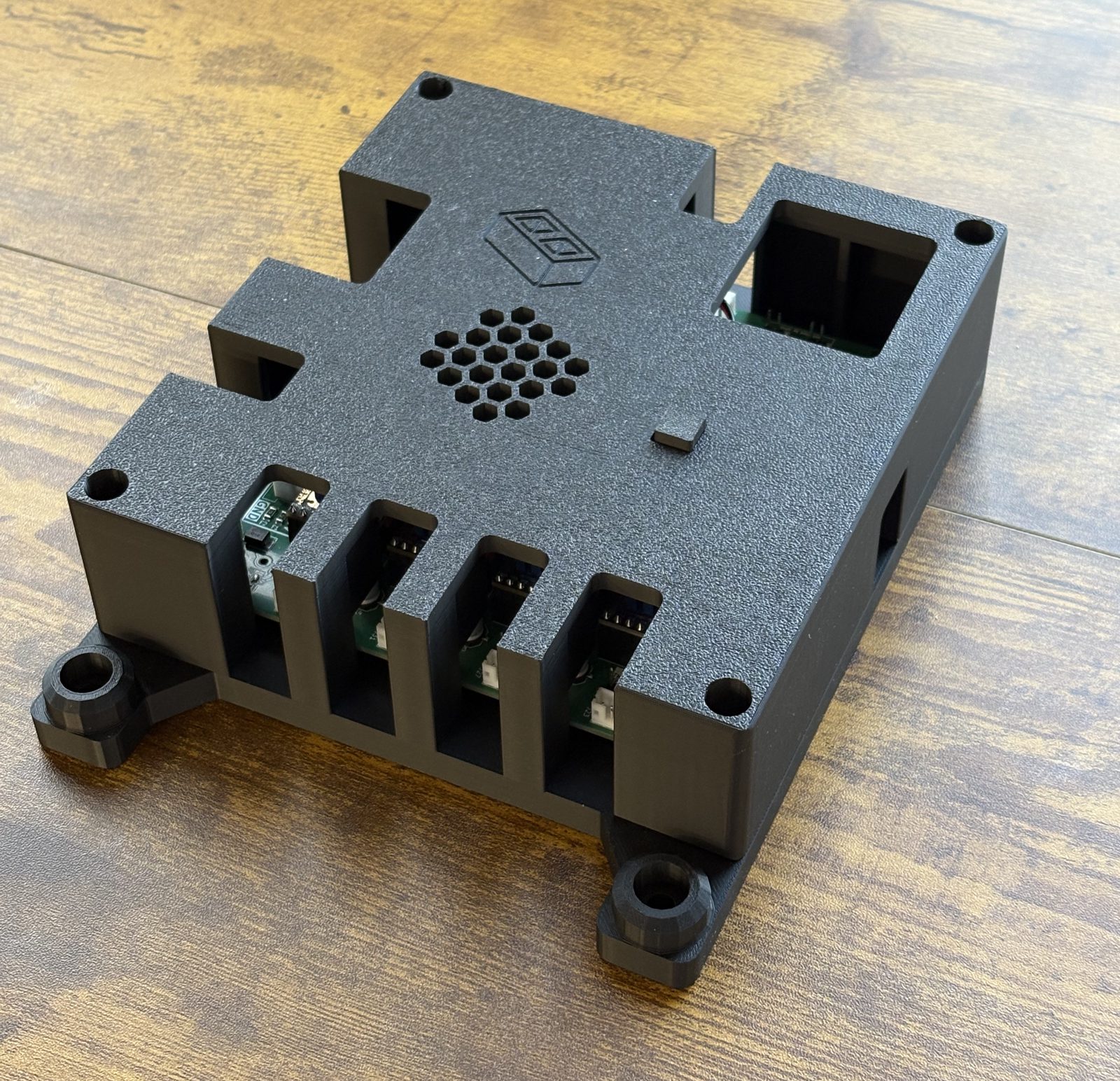
The housing closed, with the fan and the reset plunger in the cover and the stepper connectors still reachable through the bays in the wall.
Bolting it to the frame is on the installation overview, once all three enclosures are built.
Next: preparing the Orange Pi.