
Electronics — PSU box
PSU box
How-to guideThe printed housing around the Mean Well LRS-350-24, its mains inlet, and the wiring inside it.
Parts needed
Power supply
- 1×
- 1×
- 1×One per machine, and the one part you probably already own.
Printed parts
- 1×
- 1×
- 1×
- 1×
- 1×
Screws
- 4× 12mm
- 8× 12mm
- 2× 8mm
Tools needed
- Hex keys, 2 mm and 2.5 mm
- Screwdriver for the supply's M3.5 terminal screws
- Pliers, for the jacks' nuts
- Multimeter, with a continuity buzzer
Make three PSU output pigtails (PJ1 to PJ3) before you start. Each is a panel-mount barrel jack with a fork terminal crimped onto each of its two leads, and they are commonly sold with the leads already on. That page builds them; step 1 here fits and wires them.

The fasteners and quantities are in the parts list above and are called out inline at each step.
Fastener icons match the parts list: the silhouette is the head shape, the colour is the thread size. M3 M4 M5 M6
Until this box is finished it has exposed mains wiring. Observe basic electrical safety precautions: do not plug a cable into the IEC inlet until the assembly is complete, the wiring is verified and both lids are on.
The five printed parts
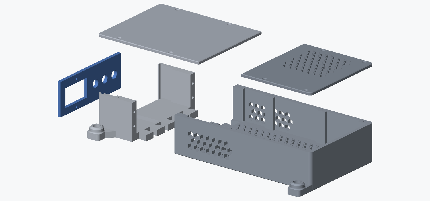
Build the front panel in your hand first. Both wiring steps are easier with it loose, and it is the last thing that goes on.
Step 1 Fit and wire the three jacks
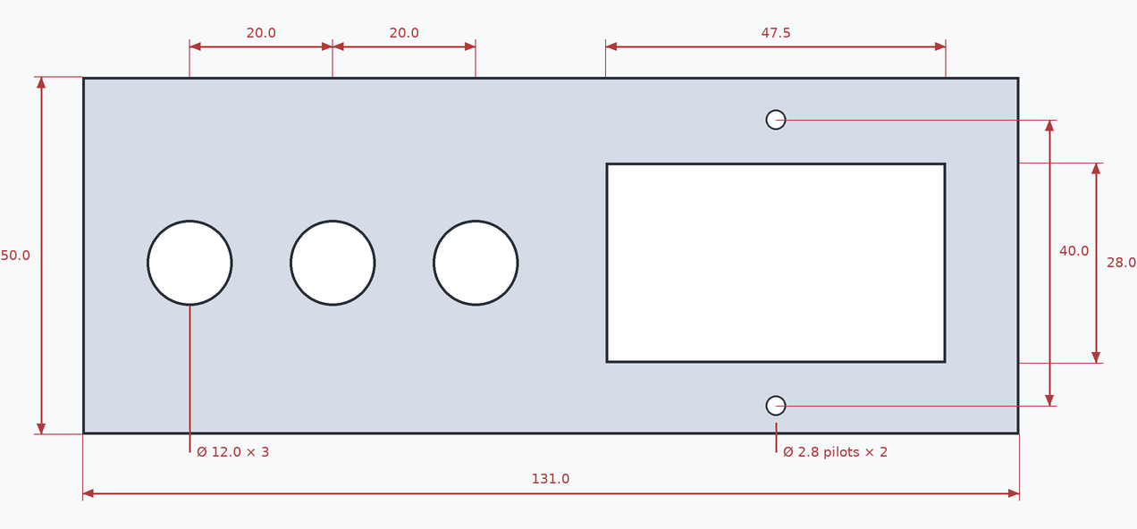
Push each jack through a round hole from the outside, so its knurled bezel sits on the outer face of the panel and the threaded barrel and the two leads come through into the box. Any of the three round holes will do.
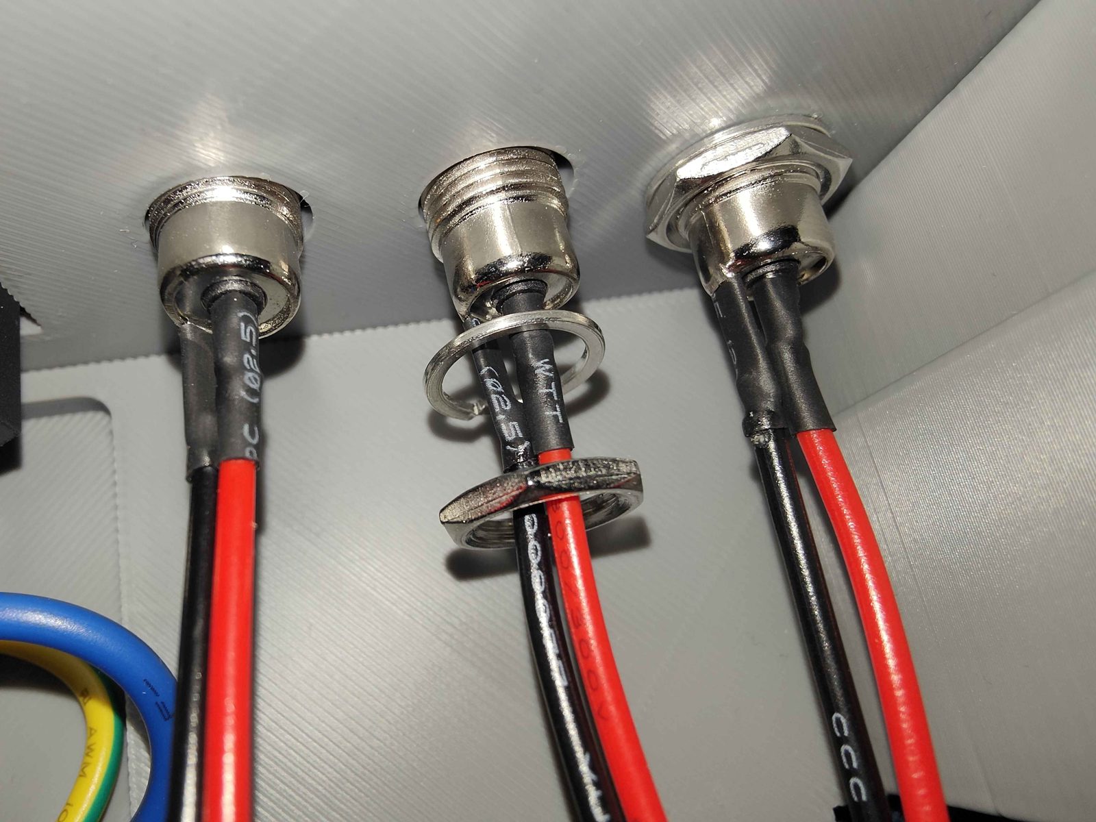
Each jack comes with a hex nut and a spring washer. Both go on the thread inside the box, in that order:
- Spring washer first, down the thread until it sits flat against the inside face of the panel.
- Then the nut, run down onto the washer and tightened until the washer has flattened out.
Without the washer the nut works loose in the printed plastic, and a loose jack turns in its hole every time a plug goes in.
Set the panel down beside the supply for now. The leads land on the terminal block in step 4, once the supply is in the tray.
Step 2 Fit the mains inlet
No mains cable (AC1) in the inlet. Not for this step, not for any of the ones after it, and not until the box is closed and the wiring checked.
The IEC C14 inlet, switch + 10 A fuse is the machine's mains entry and its on/off switch. Its three leads come already attached, so there is no AC cable to make.
The cable from the wall is an ordinary IEC C13 mains lead (AC1), the cord a desktop PC or a monitor comes with, with the plug your country uses. It is in the parts above. Three core, because the machine earths through it and out to the supply's earth screw, and 10 A or better, which matches the module's own fuse and is far more than the machine draws. It is the one part of this build most people already own, so check a drawer before buying one.
Push the inlet module into the rectangular cutout from the outside, so its flange sits flat on the outer face of the panel and its two holes line up with the panel's two small holes. The rocker can face either way, left or right, and nothing later depends on which.
Run an M3 × 8 mm countersunk into each of the two holes. Each screw cuts its own thread in the panel, and nothing goes behind it.
Stop as soon as the flange is tight. The panel bows outward before the screw gives, so the screw will not tell you when to stop.
If a screw turns and never pulls the flange down, your front panel is an older print whose holes are too wide to bite. Print the front panel again from the file in the parts list above: it is the smallest part in the set, under an hour on the plate.
Step 3 Bolt the supply into the rear tray
Set the supply's input voltage selector before it goes in the tray. The LRS-350-24 is not universal input: a small slide switch on the side of its case, marked 115V and 230V, sets which mains voltage it runs on, and it has to match the socket the machine will be plugged into. Check which way it is set now, while the supply is loose and nothing is plugged in, and slide it across if it is wrong. Once it is bolted into the tray with both lids over it you cannot reach it. Left on 115 V and plugged into 230 V mains, the supply is destroyed the moment the rocker goes on.
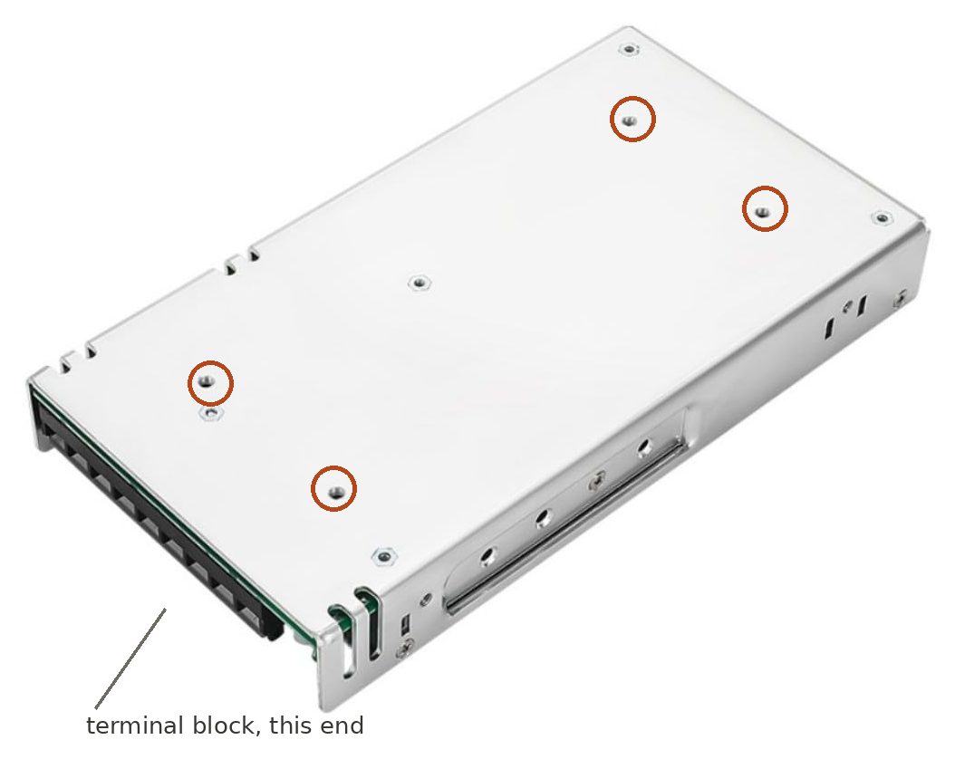
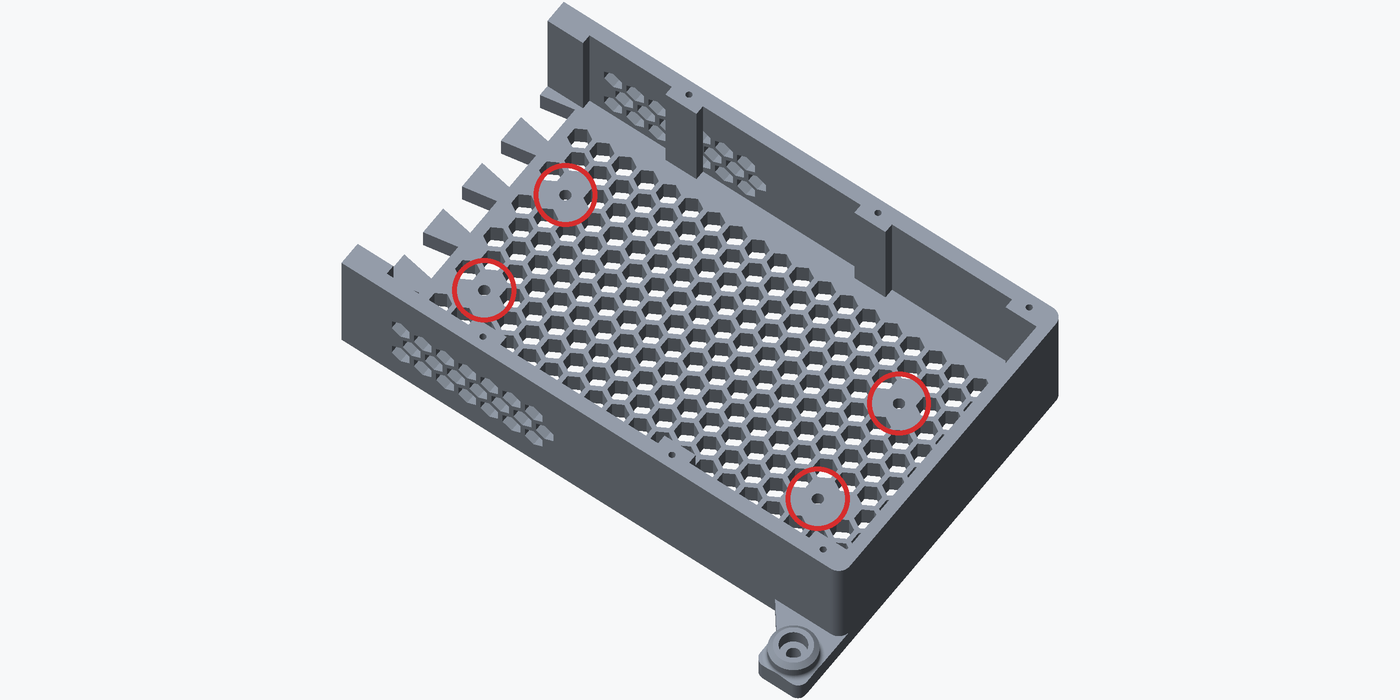
The supply's case has four threaded holes in its back face, and the tray's floor has four plain round holes that line up with them. Sit the supply in the tray and run 4 M4 × 12 mm countersunk screws up through the floor into the case.
Nothing longer goes in these four holes. The supply's circuit board is right behind that face. If a screw stops before it pulls the supply down, back it out rather than force it.
Put the terminal-block end at the open end of the tray, the end the front module butts up to. The other end is where the supply's own fan is, and that is the end the vented rear lid covers.
Step 4 Land every lead on the terminal block
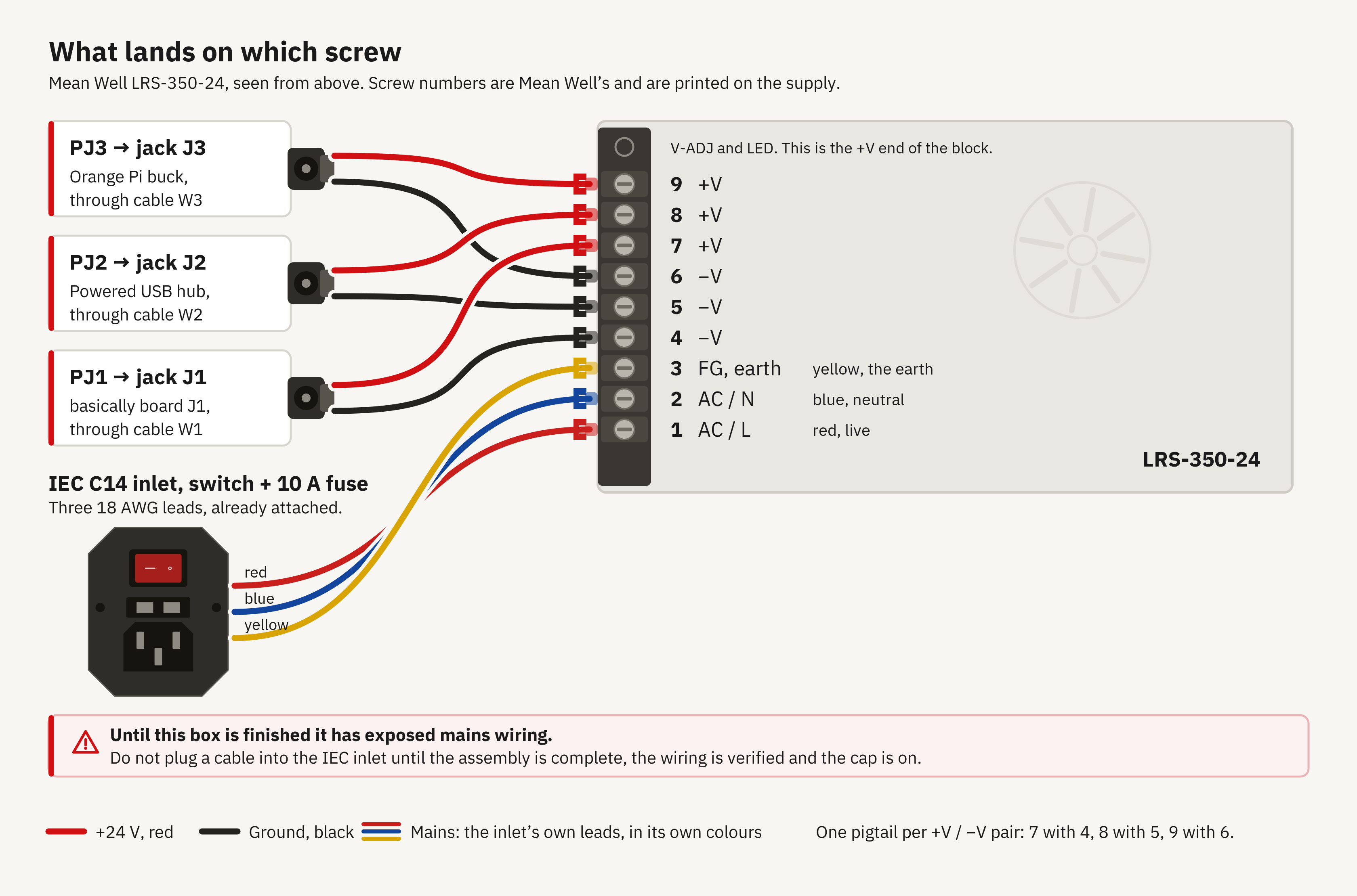
The block is nine screws and the numbers are Mean Well's own, printed on the supply beside it.
If you have been testing the inlet module on the bench, screw it into the panel first: once these leads are under the terminal screws there is no slack left to work with.
Hold the front panel up to the open end of the tray, close enough that its leads reach, and land them all:
- The three pigtails (
PJ1toPJ3), one per +V/-V pair: 7 with 4, 8 with 5, 9 with 6, the red terminal on the +V screw and the black on the -V screw of the same pair. Each pigtail must keep to one pair. - The inlet's three leads: live on 1 (AC/L), neutral on 2 (AC/N), earth on 3. The earth lead is the green-yellow one.
Find out which of the other two is live. Do not go by colour. These modules are sold with red and blue leads and both orders have been found in the post, so the colour tells you nothing about which one the fuse and the switch are in. Land them the wrong way round and the machine is fused and switched in its neutral: the supply stays live with the rocker off.
The test, with nothing plugged in: take the fuse out of its drawer, set the meter to continuity, and probe from each coloured lead to each of the two flat pins inside the C14. The pair that still beeps with the fuse out is neutral. The one that beeps only with the fuse back in and the rocker on is live, because the fuse and the switch sit in the live side. That lead goes on screw 1.
Nothing tinned goes under a screw terminal. Solder cold-flows under a clamped screw, so a tinned end that is tight today is slack in a few months, and a slack joint carrying this much current heats up. Use the fork terminals this page calls for. If you would rather put a bare lead straight under the screw, cut the tinned end off first and clamp clean stranded copper.
For each one: back the screw off a few turns, slide the fork terminal in under it, and tighten it down. Mean Well's figure for these M3.5 screws is 8 to 10 kgf·cm, about 0.8 to 1.0 N·m, which is firm rather than hard. Tug-test each terminal once it is down.
Step 5 Close the box
Slot the front panel down into the front module, either way up, then bring the front module up against the tray so the two shells meet. Lay the leads so none of them rests against the mains screws.
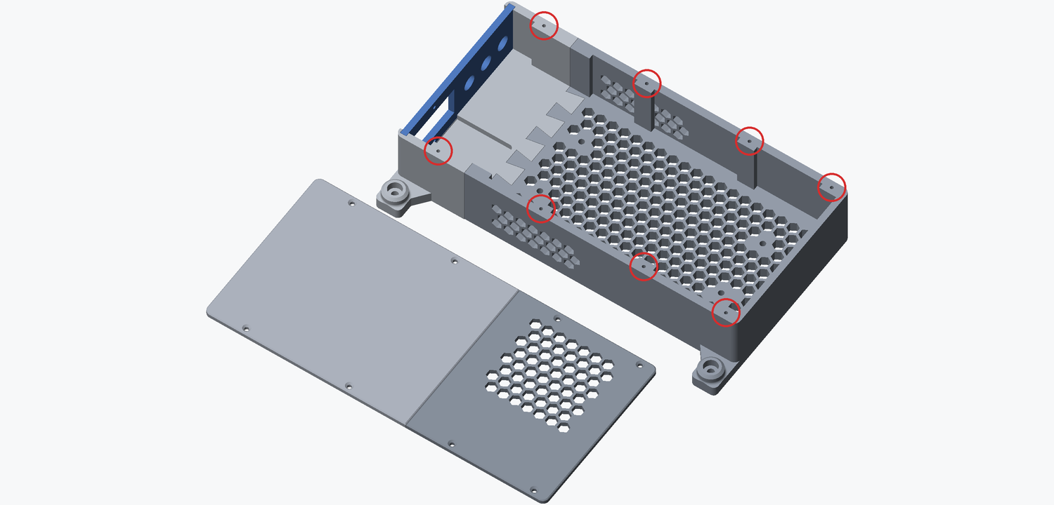
Then the two lids, 8 M3 × 12 mm countersunk . They cut their own thread in the shell parts, so run each one in until the lid is tight and stop.
- Rear lid, the vented one, over the supply's fan end.
- Front lid, over the other end. It traps the front panel, so check the panel is fully seated before it goes on.
The box is closed before the machine sees mains.
The finished result
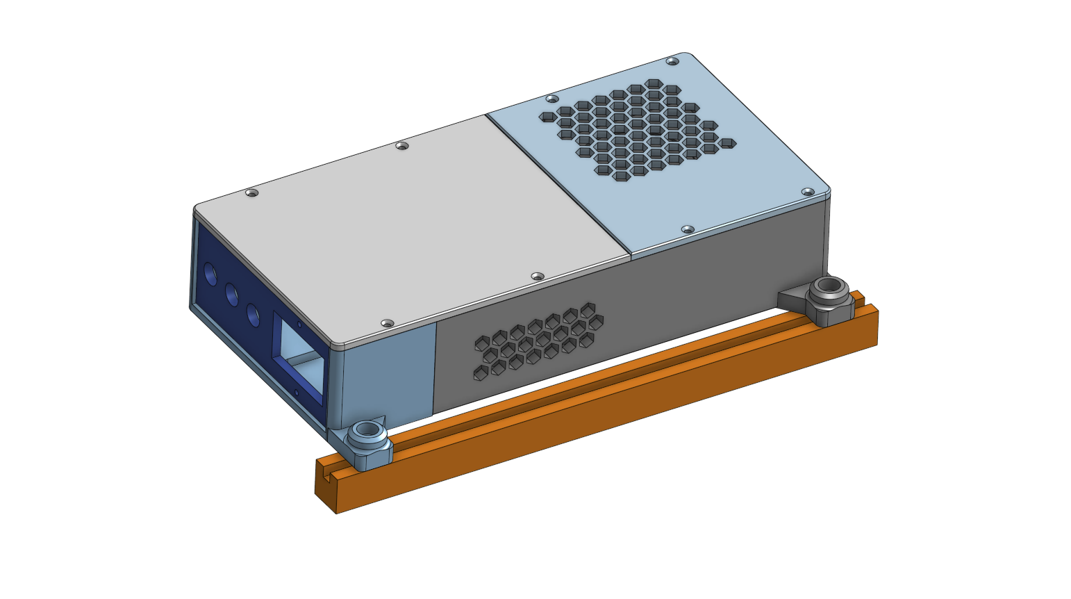
The supply inside the closed housing, both lids down, the mains inlet and the three jacks in the front panel, and the two clamp bosses ready for the frame.
Once it is in service, pull the cord (AC1) out of the wall before you open this box. The rocker is not an isolator you can rely on: a plug that goes in either way round means the switch may be breaking the neutral rather than the live, so treat everything inside as live whenever the cord is in.
Bolting it to the frame is on the installation overview, once all three enclosures are built.
Next: preparing the control board.