
Electronics — Preparing the control board
Preparing the control board
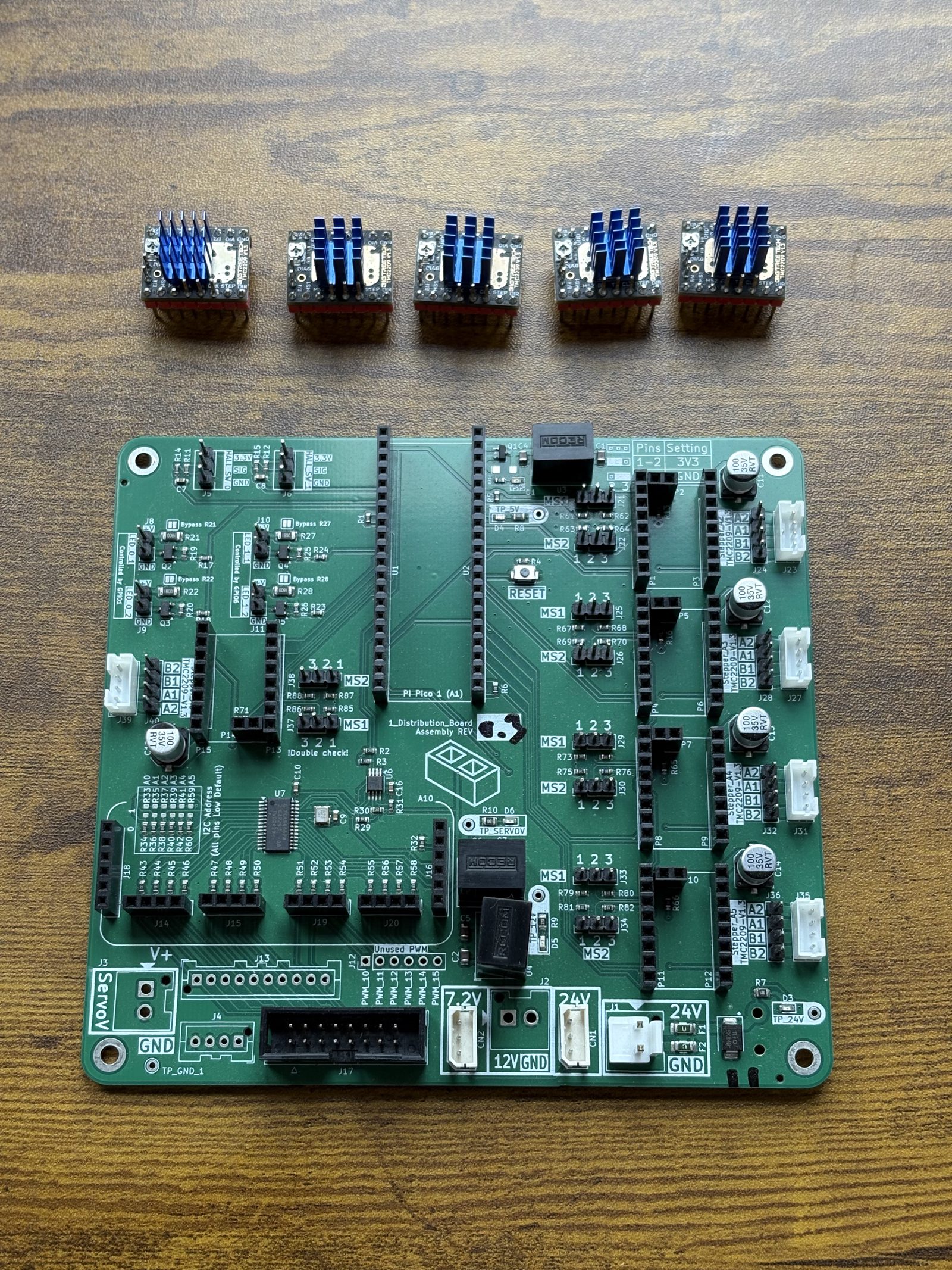
How-to guideThe five stepper drivers, the Pico, the jumpers that address the drivers, and the bypass jumpers on the four LED ports.
Parts needed
Custom PCBs
- 1×
Electronics
- 5×
- 1×
- 10×
A an interchangeable alternative works (hover for what).
Tools needed
- Soldering iron and solder
- Tweezers or needle-nose pliers
Do this with the board loose, before the housing.
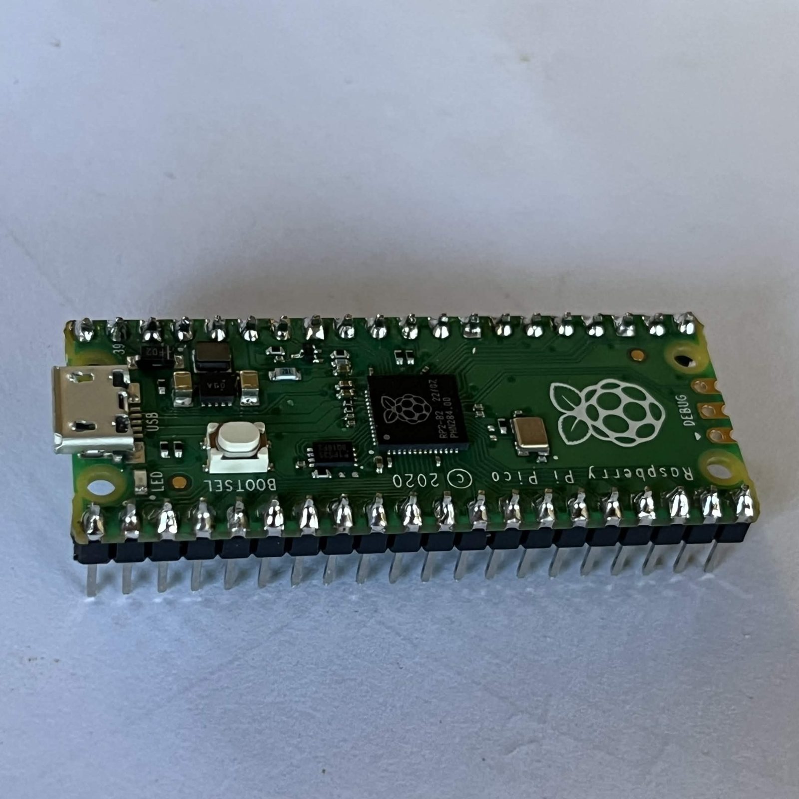
The Pico comes with its two rows of 20 pins already fitted. That is what the parts list above buys, and step 2 here only pushes it into its sockets. A bare Pico and 40 header pins do the same job if you would rather solder them on yourself.
Step 1 Seat the five drivers
Static caution: the TMC2209 modules and the board are ESD-sensitive. Touch a grounded metal surface before handling them, and avoid doing this on carpet in dry weather.
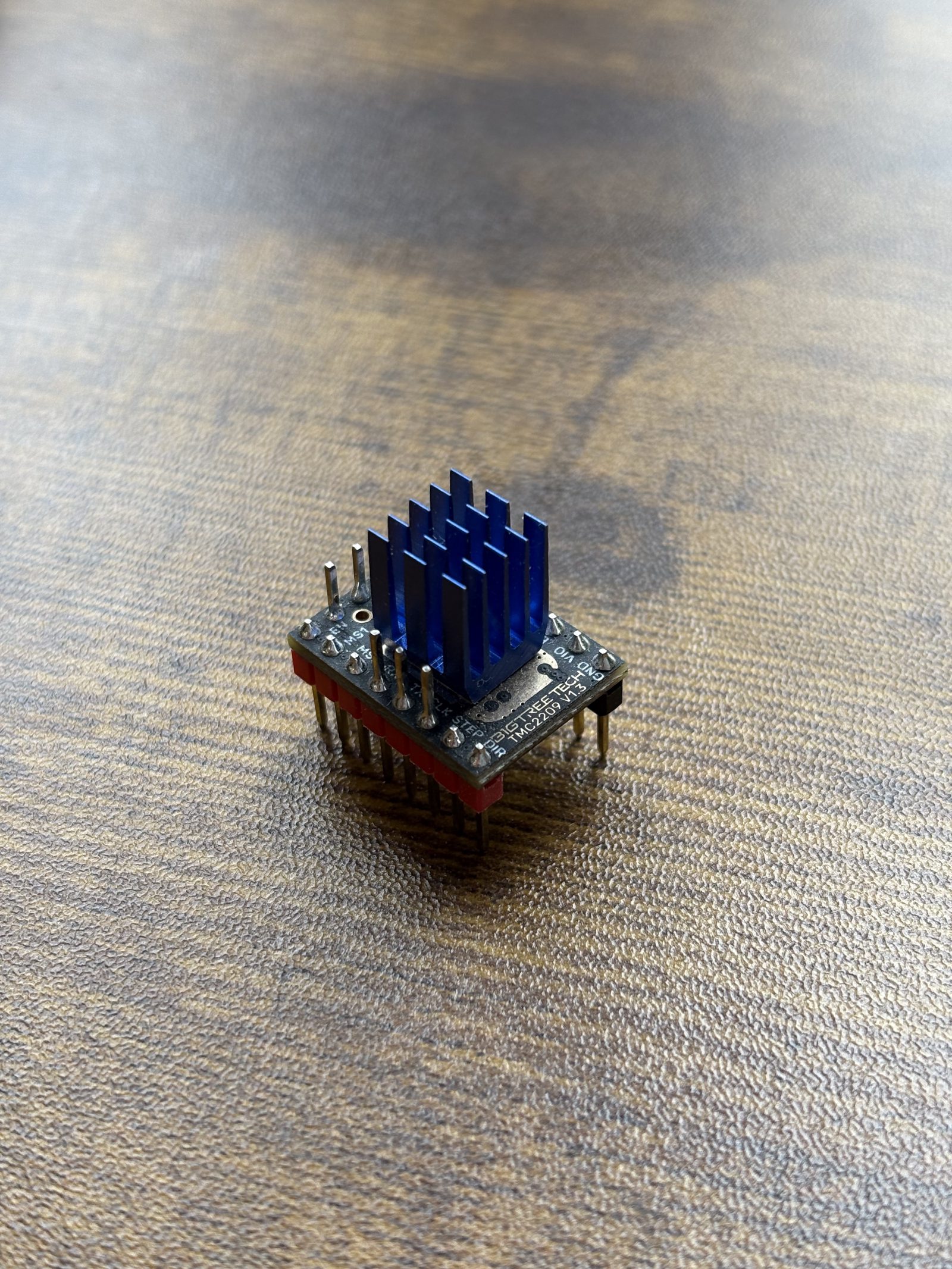
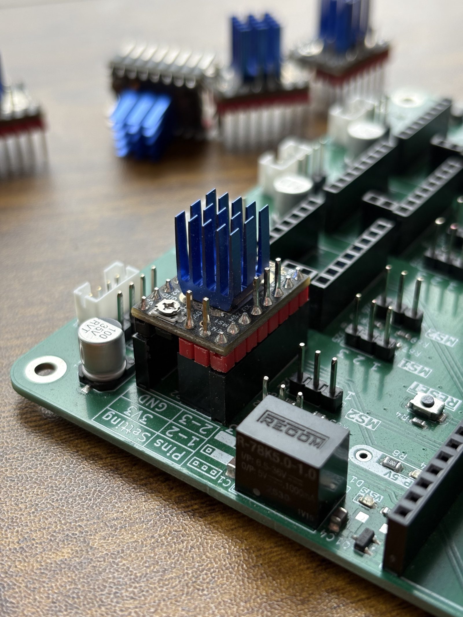
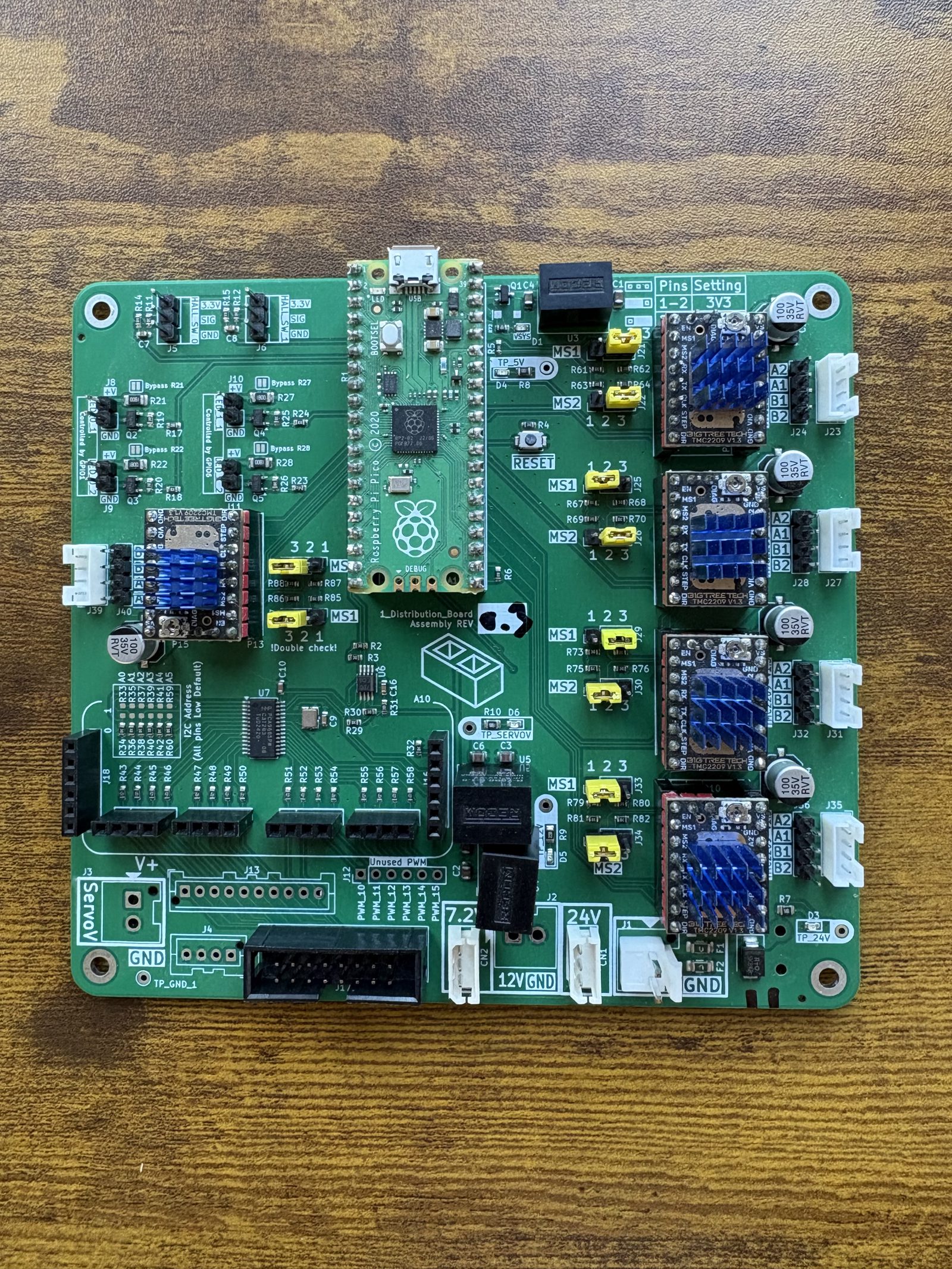
Heatsink up, EN/MS1/MS2 edge towards the middle of the board. Module and socket are both silkscreened, so match the labels. A reversed module can be damaged the moment power is applied, so double-check against the photo before moving on.
Step 2 Seat the Pico
Into the two long sockets down the middle, USB end towards the edge of the board.
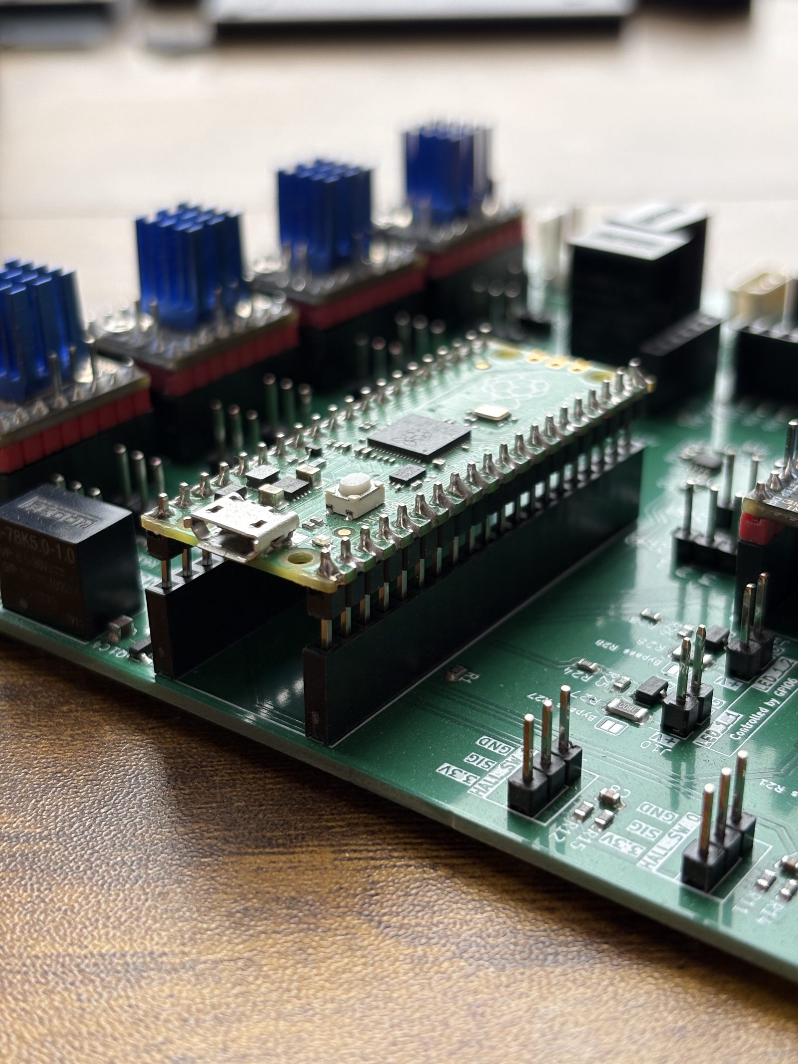
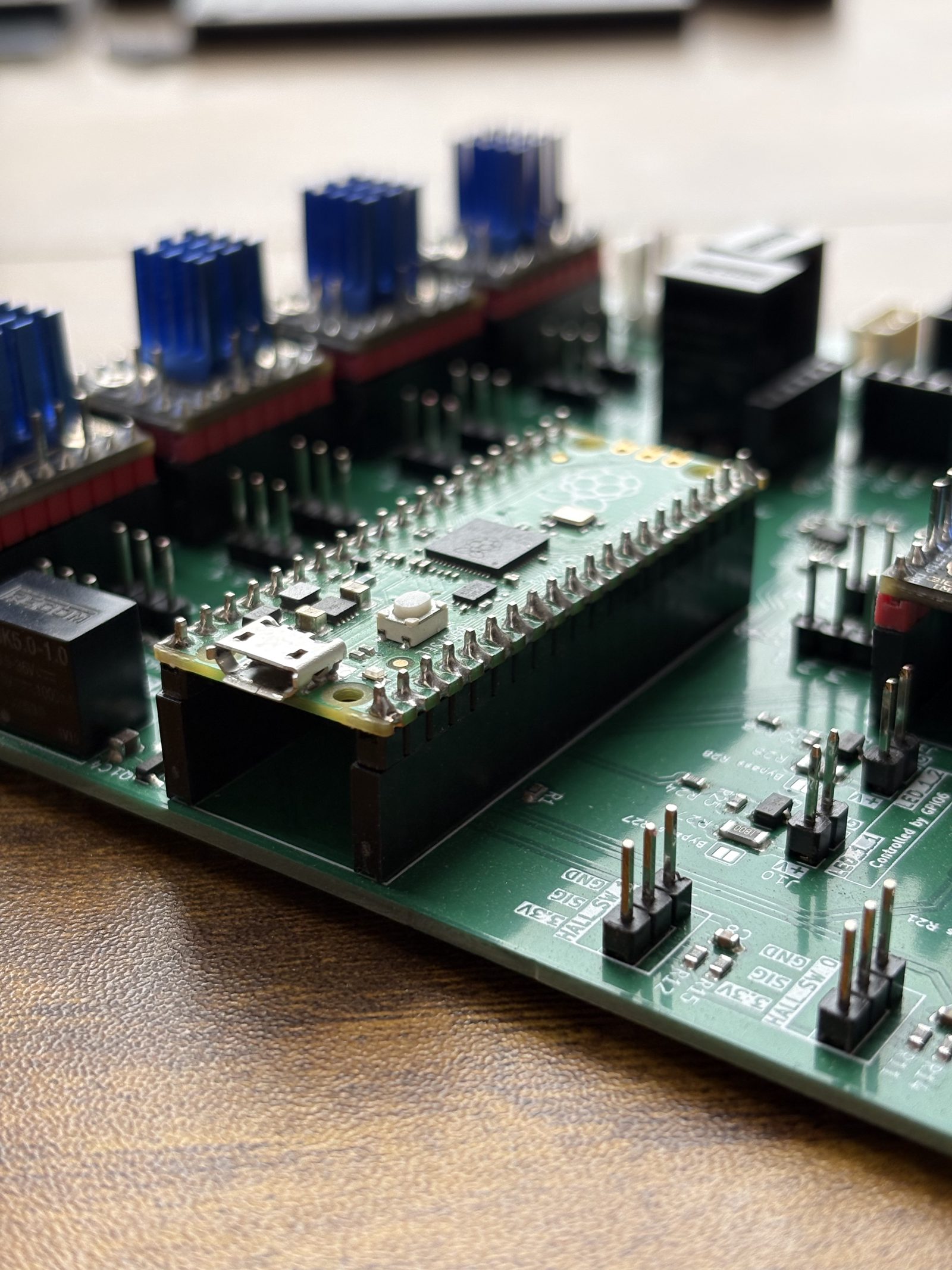
Step 3 Set the address jumpers
The five drivers share a UART bus, so each needs its own address. You set it by bridging the MS1 and MS2 header pins: 1-2 bridged reads 3V3 (HIGH); 2-3 bridged reads GND (LOW). MS1 is the low bit of the two-bit address. Two pins allow four addresses, one short of five steppers, so the board runs a second bus for the fifth driver. Ten jumpers in total, two per driver; tweezers or needle-nose pliers make placing the small 2.54 mm (0.1 in) jumper caps much easier.
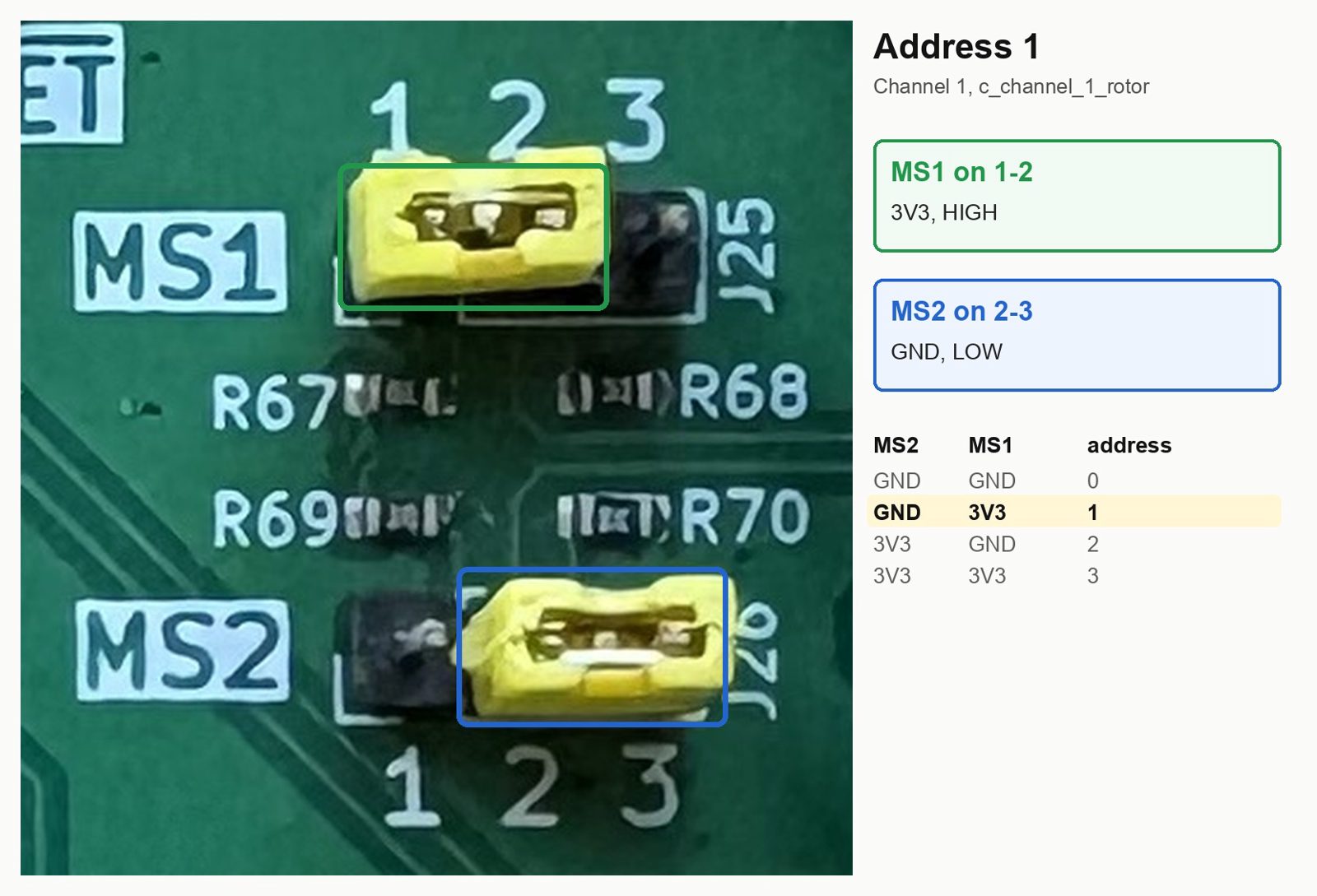
Which driver is which channel is fixed by the board, not by you: each driver socket is wired to its own pins on the Pico, and to the pair of stepper connectors beside it. The board prints the name of each one beside it, Stepper_A2 to Stepper_A6, so set the jumpers by that name.
| Printed on the board | Its stepper connectors | Channel | Stepper | Bus | Address | MS1 | MS2 |
|---|---|---|---|---|---|---|---|
Stepper_A2 | J23 / J24 | 0 | chute_stepper | uart0 | 0 | GND (2-3) | GND (2-3) |
Stepper_A3 | J27 / J28 | 1 | c_channel_1_rotor | uart0 | 1 | 3V3 (1-2) | GND (2-3) |
Stepper_A4 | J31 / J32 | 2 | c_channel_3_rotor | uart0 | 2 | GND (2-3) | 3V3 (1-2) |
Stepper_A5 | J35 / J36 | 3 | carousel | uart0 | 3 | 3V3 (1-2) | 3V3 (1-2) |
Stepper_A6 | J39 / J40 | 4 | c_channel_2_rotor | uart1 | 0 | GND (2-3) | GND (2-3) |
The two connectors in each pair are the JST-PH socket and the row of 2.54 mm (0.1 in) pins beside it, wired to the same four nets. Nothing plugs into them yet: the motors go on at connecting the components, step 2.
Read the 1 2 3 printed beside every header. The fifth driver's block is mirrored, which is why the board prints !Double check! next to it, and a wrong address fails silently: that driver never answers and its stepper stays unconfigured.
Step 4 Bridge the bypass jumpers on the LED ports
The board has four LED ports, and each one feeds +24 V through a 180 Ω resistor: R21 on J8, R22 on J9, R27 on J10, R28 on J11. That resistor is there for a bare LED board, which has no current limiting of its own. Nothing this machine plugs into those ports wants it: the camera lamps run LED strip, which limits its own current, so the resistor only costs brightness, and brightness is set with PWM in the software instead.
Bridge all four. Beside each port is a two-pad solder jumper, printed Bypass R21, Bypass R22, Bypass R27 and Bypass R28. Melt a blob of solder across both pads of each so they are joined. Nothing is added to the board (Jon, 2026-09-13 and 2026-09-23).
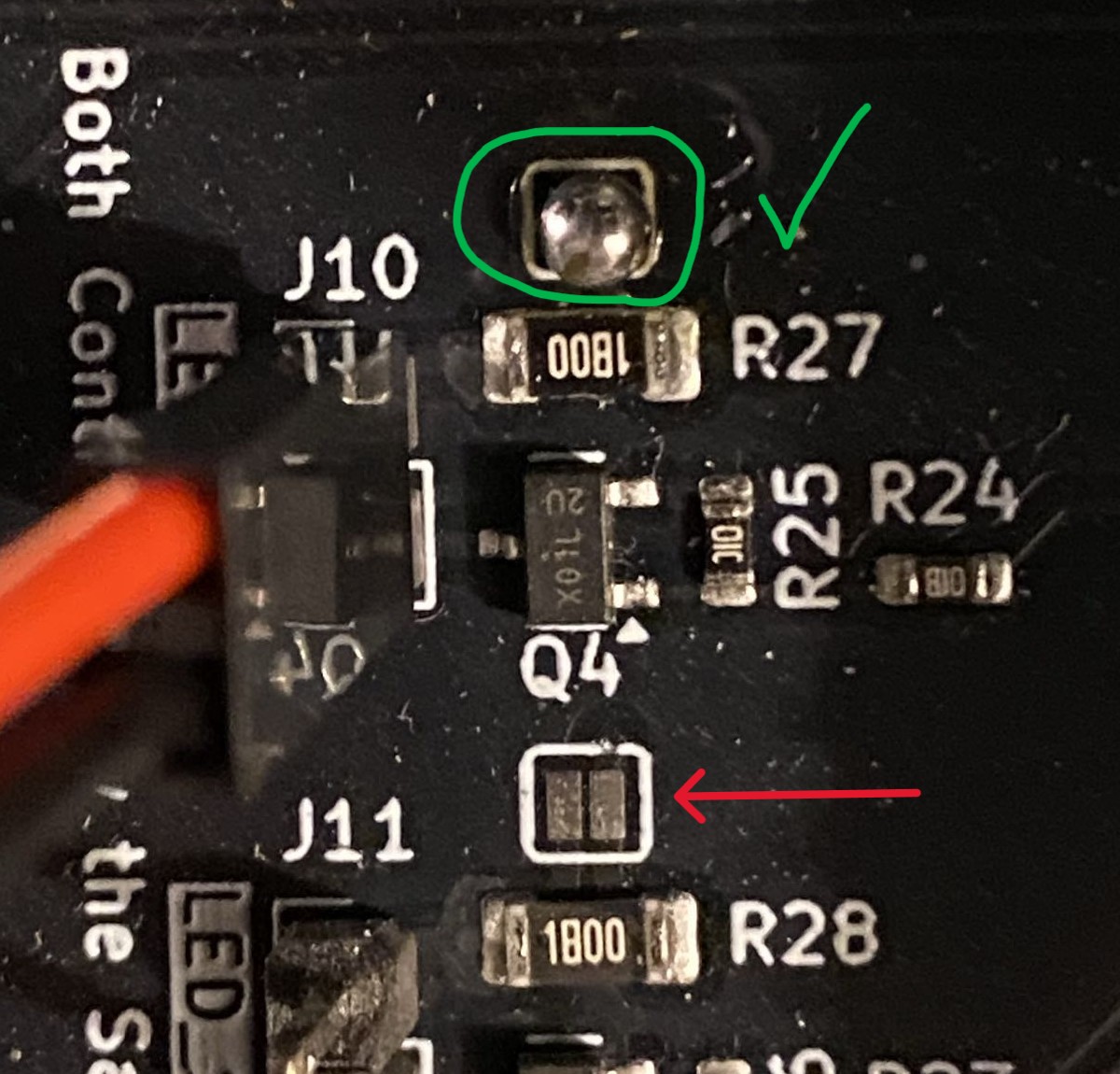
Do it now, while the board is loose. Once it is closed into its housing and wired, the pads are under the lid and behind a dozen cables. Which port takes which lamp is picked on the connecting page.
The finished result
This is a correctly jumpered board.
Next: the control board housing.