
Electronics — Orange Pi housing
Orange Pi housing
How-to guideThe Orange Pi 5 closed into its printed housing, with the USB hub and the buck converter clamped to its roof.
AI-generated first draft. Written from the machine assembly tree in the parts calculator, not from an actual build, so nobody has put this housing together from this page yet. The parts and the screws come from the CAD assembly.
Parts needed
Printed parts
- 1×
- 1×
- 1×
- 1×
- 1×
- 1×
- 1×
- 1×
- 1×
- 1×
- 1×
- 1×
Computer
- 1×
Wire harness
- 1×
Heat inserts
- 8×
Screws
- 4× 6mm
- 15× 12mm
- 1× 8mm
A an interchangeable alternative works (hover for what).
Tools needed
- Hex key, 2 mm
- Soldering iron or heat-set insert press
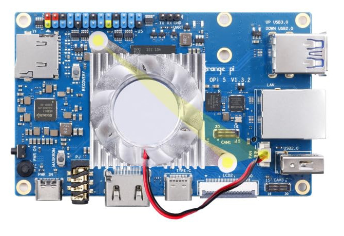
Prepare the Orange Pi before you start. The heatsink fan and the WiFi module both need both faces of the board reachable, and the housing closes around it. Not covered here.
The fasteners and quantities are in the parts list above and are called out inline at each step.
Fastener icons match the parts list: the silhouette is the head shape, the colour is the thread size. M3 M4 M5 M6
Step 1 Preparation
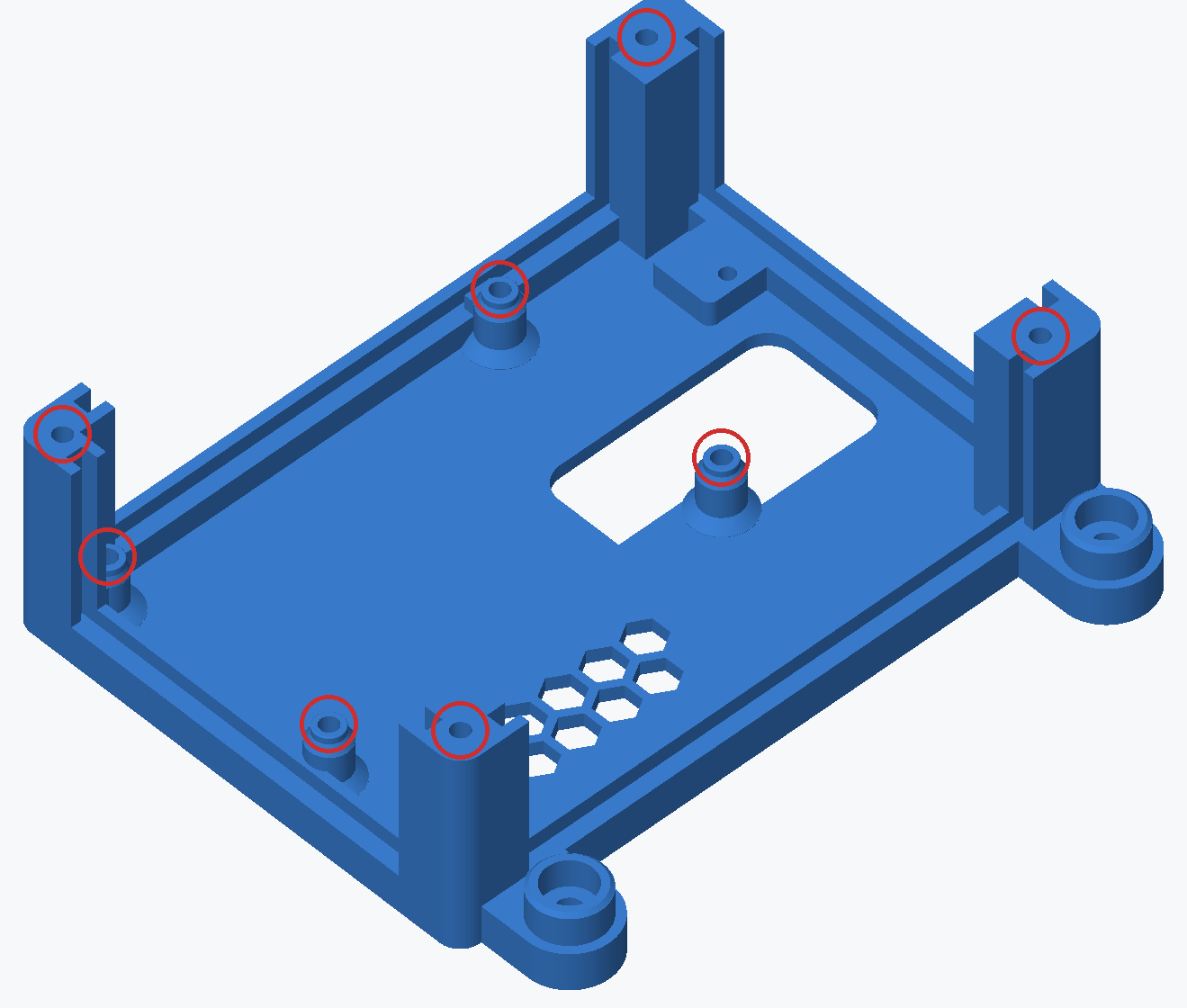
Press 8 M3 inserts into the base while it is loose: four in the low posts the Pi sits on, and four in the tall corner posts the roof screws into. See installing heat inserts. Nothing else takes one.
Orange Pi Housing base: 8 × M3
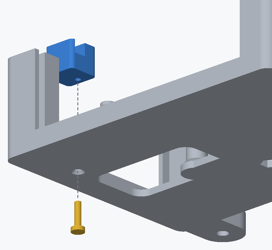
Fit the plunger retainer now, while the base is loose. Its screw goes in from underneath, and once the walls are in you cannot turn the base over without dropping them out.
Sit the retainer on its landing, at the end of the base with the large opening in its floor, and fix it with 1 M3 × 12 mm countersunk up through the base from below. It cuts its own thread in the plastic, so take it by hand.
Step 2 Screw the Pi down
Static caution: the Orange Pi is ESD-sensitive like any other bare board. Touch a grounded metal surface before handling it, and avoid doing this on carpet in dry weather.
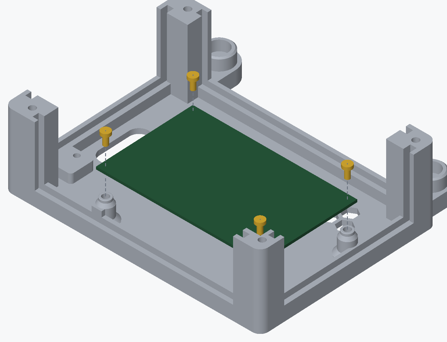
Sit the Pi on the four posts with its Ethernet and USB-A ports at the end furthest from the large opening in the base's floor, and fasten it with 4 M3 × 6 mm socket / button head screws into their inserts. It fits the posts either way round, and only this way puts its ports behind the openings in the walls.
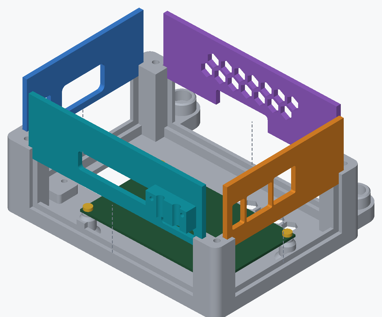
Step 3 Drop the walls in
Each wall drops into its own groove in the base, and each one only fits one side, because its openings line up with the ports on that side of the Pi:
- West, the short wall with a small square window for the power button plunger and a larger window onto the microSD card.
- East, the short wall with the openings for the USB-A and Ethernet ports.
- North, the long wall with the opening for the USB-C and HDMI ports and a block on its outside that carries the WiFi antennas. The two antennas came with the WiFi module and are already plugged into it from preparing the Orange Pi; feed them out through the slot at the bottom of the wall, under that block, as it goes in.
- South, the long wall with the hex vent, and an opening at the bottom for a cable off the GPIO header.
Nothing screws the walls in. The roof holds them down in step 6.
Step 4 Fit the power button plunger
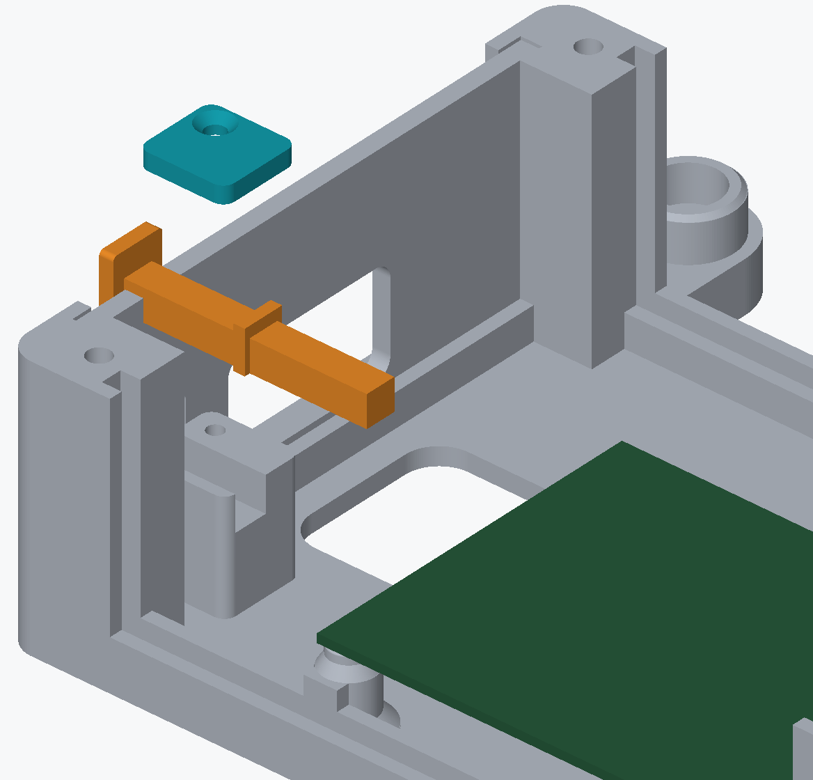
The plunger reaches the Pi's power key from outside the west wall, so the Pi can be switched on with the housing shut.
Lay the plunger in its retainer with its square face out through the small window in the west wall, and close the plunger cap over it with 1 M3 × 8 mm countersunk . The screw cuts its own thread in the plastic, so take it by hand. Press the face from outside and check that it reaches the power key.
Step 5 Clamp the antennas
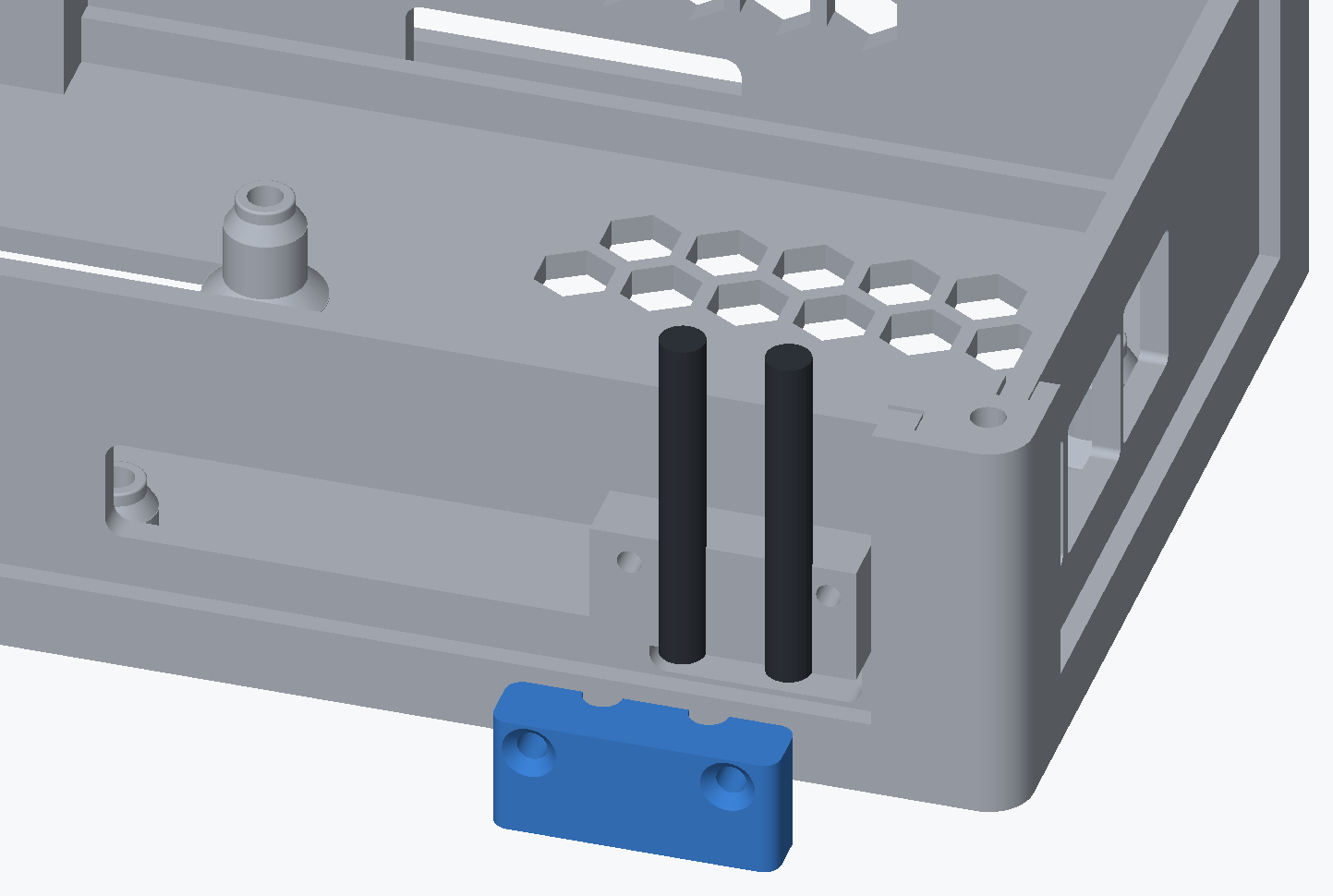
Sit the two WiFi antennas in the two channels in the north wall's block, and screw the antenna clamp over them with 2 M3 × 12 mm countersunk , self-tapping into the wall. Skip this step if the Pi has no WiFi module.
Step 6 Put the roof on
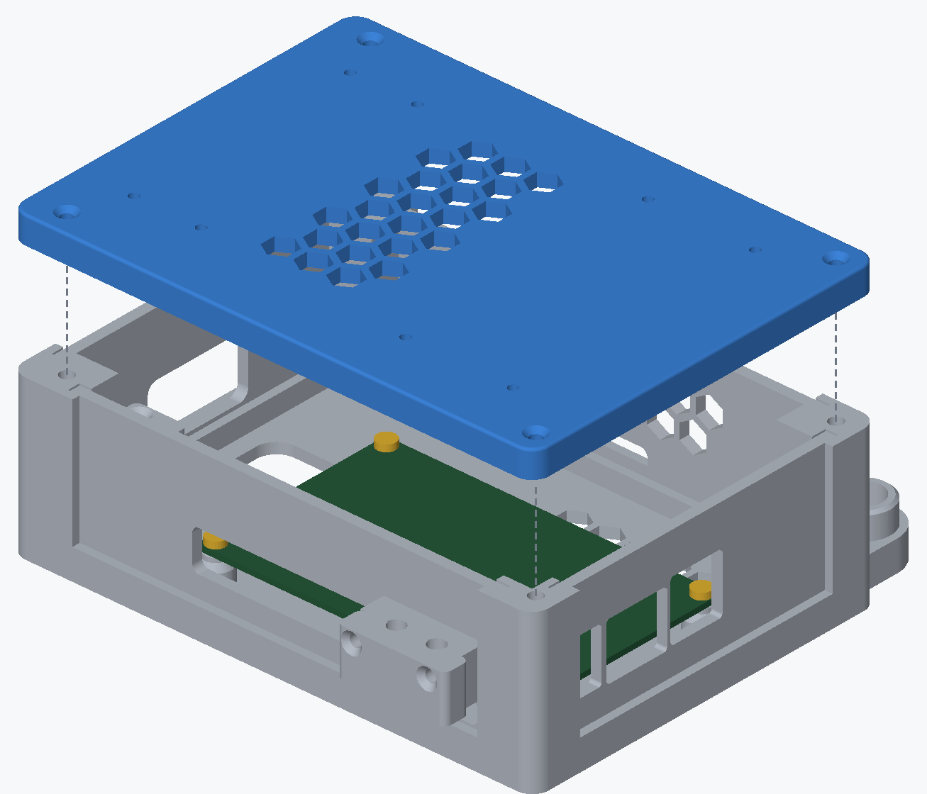
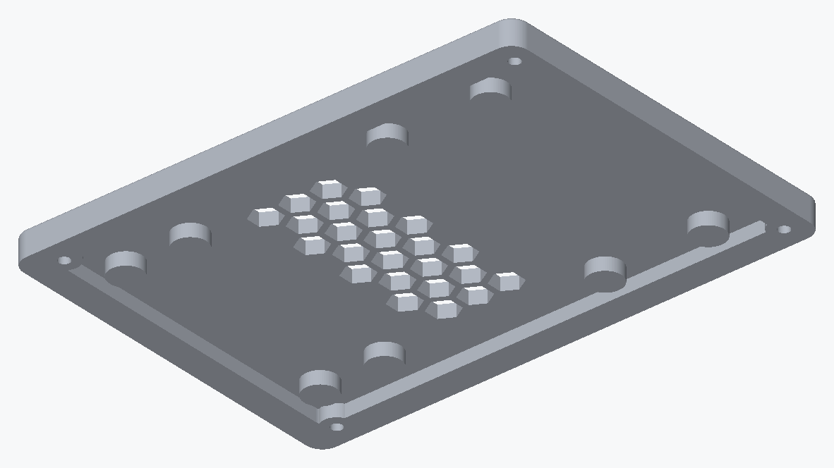
Lower the roof onto the walls grooved side down. The groove runs all the way round the underside and the tops of the four walls sit in it; on the face that ends up outside, the four corner screw holes are countersunk. Fix it with 4 M3 × 12 mm countersunk into the inserts in the corner posts.
The microSD card stays reachable with the roof on, through the window in the west wall and the opening in the floor under it.
Step 7 Clamp the hub and the buck converter to the roof
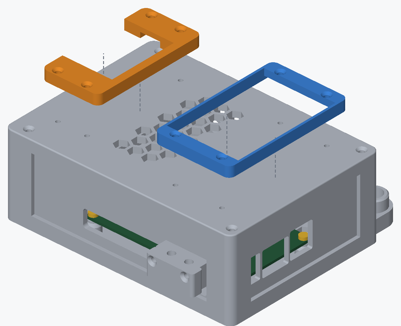
The powered USB hub sits on the roof under the hub clamp, the closed rectangular frame, and the 24 V to 5 V buck converter under the buck clamp, the open U. Each clamp takes 4 M3 × 12 mm countersunk , self-tapping into the pilots in the roof: take them by hand and stop as soon as the clamp is down.
The hub clamp is drawn around the Waveshare USB3.2-Gen1-HUB-4U. The cables into the hub and the converter (W2, W3, U1, U2) are on connecting the components.
The finished result
The housing closed on the bench, with the hub and the buck converter clamped to the roof.
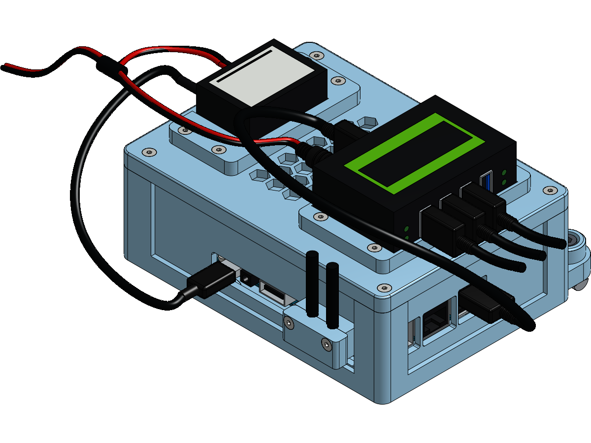
Bolting it to the frame is on the installation overview, with the other two enclosures. Its power comes from the buck converter on its roof, fed 24 V from the PSU box rather than from the control board.
Next: connecting the components.