
Helpers — Chute stepper lead (CH)
Make the chute stepper lead (CH)
How-to guideThe only stepper cable you build (CH). A 24 AWG (0.20 mm²) tail onto the motor's four bare leads, then a 4-pin housing in the right coil order. One per machine.
Parts needed
Wire harness
- 1×Board end of S1 to S4 and CH.
- 6×Twenty-six per machine: twenty on the cables and six spares.
- 6×Four on the chute stepper cable, one on each of the motor's leads, and two spares.
- 1×Four colours, for the chute stepper cable.
- 1×Optional. About 1 m (39 in) over the four wires.
A an interchangeable alternative works (hover for what).
Tools needed
- Multimeter, to find the coils and to check the finished lead
- Side cutters, to cut the tail wire to length
- Wire strippers that take both 24 AWG (0.20 mm²) and 20 AWG (0.52 mm²) wire
- Insulated-terminal crimping pliers with a die marked for 24 to 20 AWG (0.2 to 0.6 mm²), for the four butt splices
- Crimping pliers for open-barrel contacts, with a die for 24 AWG (0.20 mm²) wire, for the four PH contacts
- A ruler or tape measure, to cut the tail to length
- Only if you solder the splices instead: soldering iron and solder, adhesive-lined heat shrink, and a heat gun to shrink it
- Optional, for the sleeving: scissors and tape, or a hot knife
The chute stepper is the NEMA 23 that drives the chute. It is the only motor on the machine with bare flying leads: the four channel steppers have their own 6-pin socket, and their own lead (S1 to S4) that you re-house with a PHR-4. So this one lead (CH) gets built from the motor's bare leads. One per machine. The parts list has six butt splices and six PH contacts, two more of each than the lead uses: the first crimps on a new part are easy to spoil. General help with crimping is at Crimping connectors.
The motor's own leads are too thick for the connector, however long they are. They are 20 AWG (0.52 mm²) (UL1007 on the motor drawing) and a JST PH contact takes 24 to 28 AWG (0.08 to 0.20 mm²), so the board end of this lead is always a short 24 AWG (0.20 mm²) tail spliced onto them. Length decides how long that tail is, not whether you need one. A butt splice made for 24 to 20 AWG (0.2 to 0.6 mm²) holds both sizes, so the splice is crimped.
The pin order
All five stepper outputs on the board have the same pinout, pin 1 to pin 4:
| Position | Net | Coil |
|---|---|---|
| 1 | A2 | coil A |
| 2 | A1 | |
| 3 | B1 | coil B |
| 4 | B2 |
Position 1 is the pin on the square pad. A PH housing is keyed and only plugs in one way round, so the PHR-4 goes on with its position 1 over that pad. A Dupont housing is not keyed and fits either way up, and nothing moulded on it tells you which end is 1, so go by the pad: the first wire goes over the square one. Turned half a turn it still goes on, with the wires in reverse order. Nothing is damaged, but the motor then turns the other way, so check the direction in the software.
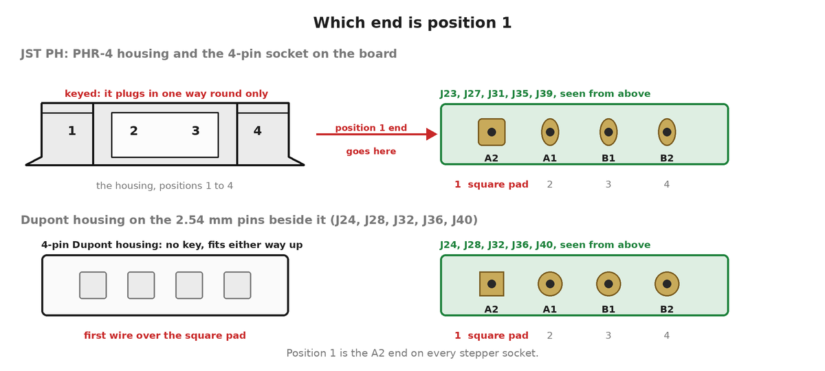
Positions 1 and 2 are one coil, 3 and 4 are the other. Swapping the two wires inside a coil only reverses the direction the motor turns. Splitting a coil across the 2 and 3 boundary is what stops it working, so keep each pair together.
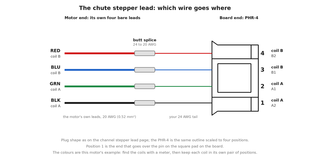
CH) end to end: each of the motor's leads is spliced onto a thin tail, and the tails go into the PHR-4. Each coil stays in its own pair of positions.The full pinout and the board-side footprint are on the wire harness page.
Find the coils first
The motor's four leads are coloured, and the colours do not tell you which pair is which coil on every motor.
- Set the multimeter to resistance, the Ω position on its dial.
- Put a probe on two of the four leads. A pair from the same coil reads well under an ohm on this motor, 0.65 Ω at the winding plus whatever your probe leads add. Two leads from different coils read open circuit, which most meters show as
OLor a lone1. - Work through the leads until you have both pairs. Write down which colour goes with which.
Build it
- Decide the tail length. The harness schedule lists
CHas a 300 mm (12 in) tail: that is the wire you cut, and it is enough for any motor, because the motor's own leads come out at 300 to 500 mm (12 to 20 in) depending on the batch. Overall the finished lead is then about 600 mm (24 in) with 300 mm leads, and up to about 800 mm (31 in) with 500 mm leads. If you would rather not have the extra, hold the motor where it will sit, and cut the tail to about 600 mm (24 in) minus the length of the motor's own leads: 100 mm (4 in) for 500 mm (20 in) leads, 300 mm (12 in) for 300 mm (12 in) leads. - Cut four pieces of 24 AWG (0.20 mm²) wire, one in each colour of the motor's four leads, the length you worked out in step 1 and never under 100 mm (4 in), even when the motor's own leads already reach.
- Splice each one onto the motor lead of the same colour with a 24 to 20 AWG (0.2 to 0.6 mm²) butt splice, as under Splicing a tail onto a motor lead, below. Or solder them, as under Or solder the splices.
- Optional: if you will sleeve the lead, slide a 1 m (39 in) length of braided sleeving over the four tails from their free ends now, before you crimp the contacts, and push it along over the splices. The 4-pin housing may not go through it, so it goes on first. Leave it bunched up on the cable for now; Sleeving (optional) says how to cut and finish it.
- Crimp a PH contact onto the free end of each of the four tails, as under Crimping a PH contact, below.
- Push the contacts into the housing until each one clicks: one coil into positions 1 and 2, the other coil into positions 3 and 4. Which coil goes in which pair does not matter. Nor does which lead of a pair goes in which position: that only reverses the direction the motor turns, and the direction is set in the software.
Splicing a tail onto a motor lead
Four joints, one per lead, each in its own butt splice. A butt splice is a clear tube with a metal barrel inside that you crimp onto a wire at each end. Use the 24 to 20 AWG (0.2 to 0.6 mm²) one in the parts list: a splice made for thicker wire does not grip a 24 AWG (0.20 mm²) tail, and one made for thinner wire does not take the motor's leads.
- Strip the end of the tail and the end of the motor lead. Hold each wire against the splice to judge how much insulation to take off, then check it in the next step and adjust.
- Push the motor lead into one end of the splice until it stops. The insulation should sit against the end of the metal barrel, and the bare strands should reach the stop in the middle. The plastic is clear, so you can see both through it. Strip a little more or less until they do.
- Crimp that end in the die of the insulated-terminal pliers marked for 24 to 20 AWG (0.2 to 0.6 mm²), with the metal barrel in the die. Choose the die by the size marked on it, not by its colour.
- Push the tail into the other end in the same way and crimp that end.
- Pull on both wires to check the joint holds.
- Make the other three joints the same way, staggered along the cable so no two sit side by side.
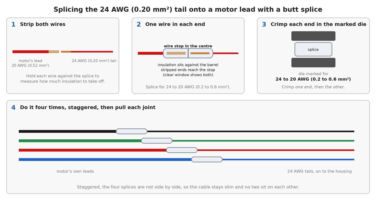
This is not the die for the PH contacts. Pliers made for open-barrel contacts, the kind that crimp the PH and Dupont contacts, do not close this splice properly. The PH contacts take their own die, below.
Or solder the splices
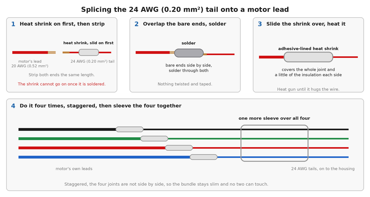
You can solder each joint instead of crimping it. The harness spec is a solder splice with adhesive-lined heat shrink, one sleeve per conductor and one over all four, and no twist-and-tape. You then need the soldering iron, solder, heat shrink and heat gun from the tools list, and you do not need the butt splices.
- Slide a piece of adhesive-lined heat shrink onto the 24 AWG (0.20 mm²) tail, well back from the end. It cannot go on once the joint is soldered.
- Strip the same length off the end of the tail and off the end of the motor lead.
- Lay the two bare ends side by side, overlapping, and solder them together until the solder has run through both sets of strands.
- Slide the heat shrink over the joint, so it covers the bare metal and a little insulation either side, and shrink it with the heat gun until it grips the wire.
- Make the other three joints the same way, staggered along the cable so no two sit side by side.
- Slide one more piece of heat shrink over all four and shrink it, so the four leave the motor as one cable.
Crimping a PH contact
A PH contact takes 24 to 28 AWG (0.08 to 0.20 mm²) wire only, which is why it goes on the tail and not on the motor's own leads.
- Strip about 2 mm (0.08 in) off the end of the tail.
- Close the contact's inner wings on the bare strands and its outer wings on the insulation, in the die of the crimping pliers marked for 24 AWG (0.20 mm²) wire.
- Pull on the wire to check it holds, then push the contact into the housing from the back until it clicks.
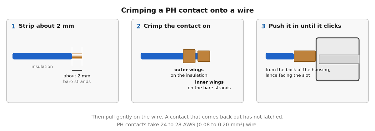
Choose the die by the size marked on it, not by its colour.
Check the coils again on the finished lead. Meter across positions 1 and 2, then across 3 and 4. Both read the same fraction of an ohm you measured at the leads. If either reads open circuit, a contact has gone into the wrong position: pull the two out and swap them. A motor wired across the coils buzzes and barely turns.
Either socket on the board takes it
The board gives the chute two sockets side by side and they are wired to the same four nets, so the lead can end in either one:
J23- JST-PH 4-pin, the housing in the parts list above.
J24- A row of 2.54 mm (0.1 in) pins, which takes a 4-pin Dupont housing instead. Use this one if you have Dupont housings and no PH contacts.
Both carry A2, A1, B1, B2 on positions 1 to 4, and the board prints the coil name beside each pin, so the names can be read off the board rather than counted.
Sleeving (optional)
You can skip this and the lead works the same. The sleeving is on the parts list as optional. It keeps the wires together as one tidy cable and protects them where the lead runs along the frame, and it is another way of securing the cables.
Where: over the four wires, from just clear of the motor to just short of the PHR-4, so it covers the four splices as well as the tail. About 1 m (39 in).
How:
- Push the braid together lengthwise to open it: it widens as it shortens. Feed all the wires into it together, so none of them is left outside.
- Cut it to length with a hot knife or a soldering iron with a blade tip, so the cut melts shut. Plain scissors leave the braid fraying. With no hot tool, wrap a turn of tape around the braid where you will cut, cut through the middle of the tape with scissors, and leave the tape on.
- Stop the sleeving 5 to 10 mm (0.2 to 0.4 in) short of the PHR-4, so the crimped contacts and the housing can flex and the sleeving never crowds into the housing.
- Hold each end with a small piece of heat shrink or a turn of tape, so that the braid cannot creep back along the wires.
Leave the sleeving loose enough to bend, and do not strap it down so tightly that it crushes the braid.
Securing the lead
When the lead is on the machine, strap it to the frame a short way back from the plug and from the motor, and leave a little slack at the plug and at the splices. Use hook-and-loop straps rather than zip ties, so the lead can come loose when you take the machine apart: see securing the cables.
The finished result
One lead (CH): the motor with a 24 AWG (0.20 mm²) tail spliced onto its four thick leads, ending in a 4-pin PHR-4 with each coil on one pair of positions.
Reference
No supplier drawing covers this lead (CH) yet. The other leads, and the rest of the harness, are on the WireViz
drawings page.
Where it goes
Onto the chute socket at connecting the components, step 2, which is also where the socket decides which motor the software drives.