
Electronics — Installation
Installing the electronics
The power supply, the control board and the Orange Pi, each built on the bench and bolted onto the same frame. Build in this order.
One of these pages (PSU box) involves wiring mains voltage. Read it fully before starting, and do not plug a cable into the IEC inlet until that box is complete and its wiring verified.
Tools needed
- Hex key, 3 mm for a button head or 4 mm for a socket head
The machine's electronics are the power supply, the control board, and the Orange Pi that runs the machine, each on its own printed part bolted to the same frame. All three are closed in: the supply in a box, the control board and the Orange Pi each in a housing. "The control board" here means basically board v1.3, the basically Embedded Control Board.
These pages cover where the hardware sits and what holds it there. What plugs into what is the other half, and that is connecting the components, with the wire harness page behind it as the reference for the cables themselves.
The Pico is bought with its header pins already fitted, so there is nothing to prepare before this list. If yours is a bare one, solder its headers on first, a one-time step under Helpers; it won't seat in the control board without them. Then:
- PSU box. The printed enclosure around the Mean Well LRS-350-24, its mains inlet, and the wiring inside it.
- Preparing the control board. The five stepper drivers, the Pico, and the ten jumpers that address the drivers. Done with the board loose.
- Control board housing. The prepared board closed into its printed housing, with the 40 mm fan and the reset plunger in the cover.
- Preparing the Orange Pi. The heatsink fan and the WiFi module, both fitted while the board is still loose on the bench.
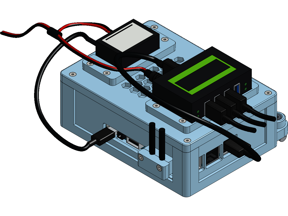
- Orange Pi housing. The Orange Pi 5 closed into its printed housing, with the USB hub and the buck converter clamped to its roof.
Every one of those pages finishes on the bench. Bolting the enclosure to the frame is one step, the same on all three, and it is on this page.
Bolting the enclosures to the frame
Each of the three printed enclosures bolts to the 2020 frame with 2 M5 screws into 2 T-nuts , 6 of each in total. The holes in all three are clearance, so the screw passes through the plastic and pulls down onto the nut.
- Orange Pi housing: 2x M5 × 16 mm socket / button head , each with an M5 washer under its head
- PSU box: 2x M5 × 16 mm socket / button head , each with an M5 washer under its head
- Control board housing: 2x M5 × 16 mm socket / button head , each with an M5 washer under its head
All three take the same screw, because every clamp boss is 10 mm deep.
The six T-nuts go into the hex frame while the top interface is built, at step 13 of that page.
No problem if you forgot them. The T-nut this build specifies is the spring-loaded roll-in kind, which drops into the slot anywhere along its length, so it can still go in now without taking the frame apart. See Fitting T-nuts.
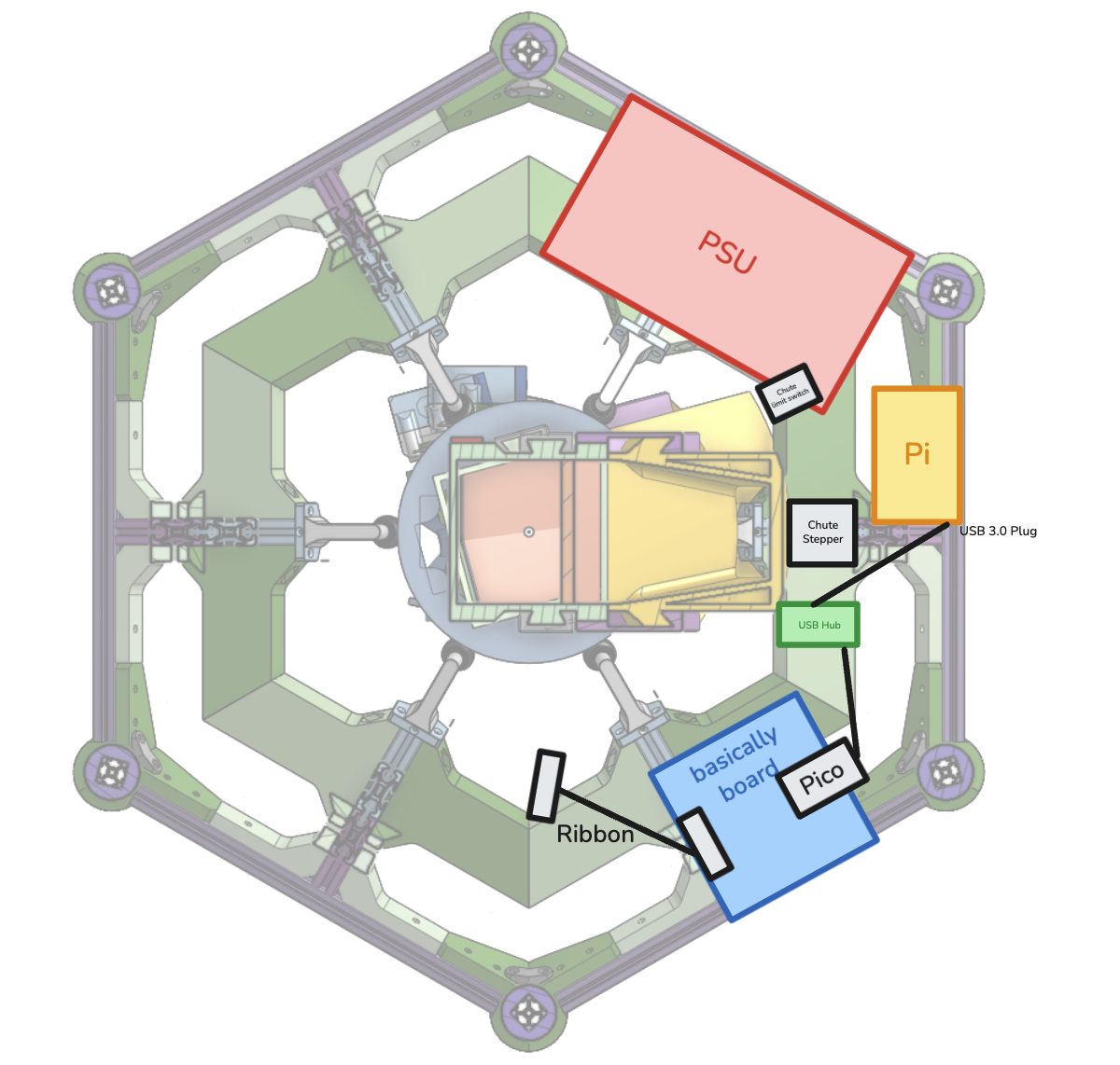
All three go on the same plane: the hex frame that belongs to the top interface, the one lowered onto the interface assembly at step 13 of the top interface build. The render below is that frame seen from above, and the chute stepper is the landmark to place the three enclosures against.
All three are bolted on from here, each once it is built and closed on its own page. None of the five pages ends with a bolting step of its own. What one looks like done is at the foot of this page.
What is not recorded yet
Collected here rather than left on the individual pages, because these are the things that block finishing them.
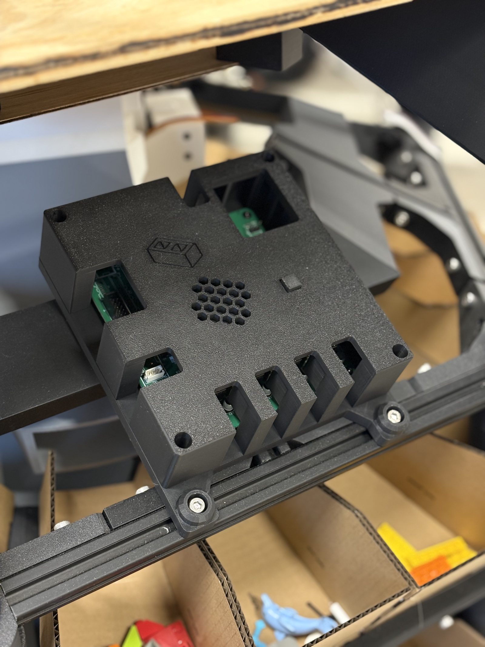
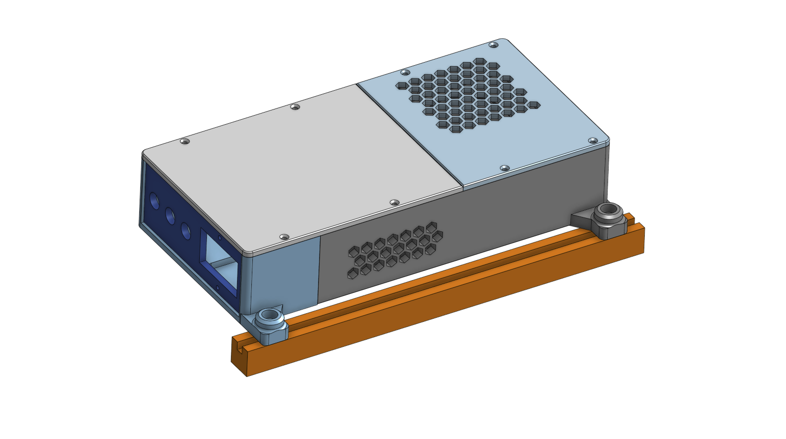
- The PSU box and the Orange Pi housing have never been photographed bolted on. The control board housing has a picture of it on the frame in the row below; the other two have renders there rather than builds.
The finished result
All three enclosures bolted onto the hex frame, each one once its own page has finished it on the bench.
With the three enclosures bolted to the frame, connecting the components plugs them together: every cable between them, and the socket each end goes into. Software setup comes after.