
Electronics — Preparing the Orange Pi
Preparing the Orange Pi
How-to guideThe WiFi module and the heatsink fan, both fitted while the board is still loose on the bench.
Parts needed
Computer
- 1×
- 1×
Electronics
- 1×
Tools needed
- Small Phillips screwdriver
Everything here is done to the board itself, before it goes anywhere near the machine, and that is the point of the page: the heatsink fan clips through the board and the WiFi module lives on its underside, so both want a board you can pick up and turn over. Once the Pi is in the Orange Pi housing there is a printed floor directly underneath it.
Which board to buy, how much memory and storage it needs, and which WiFi module fits which variant are all on the Orange Pi 5 page. This page assumes you have the parts.
The WiFi module is optional. A machine staying on Ethernet does not need it, and steps 1 to 3 are skipped, leaving only the heatsink fan. The original Orange Pi 5 has no WiFi on the board, so a machine going wireless needs either this M.2 module or a Linux-compatible USB adapter.
Step 1 Check the WiFi module (optional) matches the board
The M.2 formats used across the Orange Pi family are the same size and differ only in where the keying notch is cut into the row of gold contacts, so a module only seats in the slot it is keyed for. Which module goes with which board, and how to tell the two slots apart by eye, is on the Orange Pi 5 page.
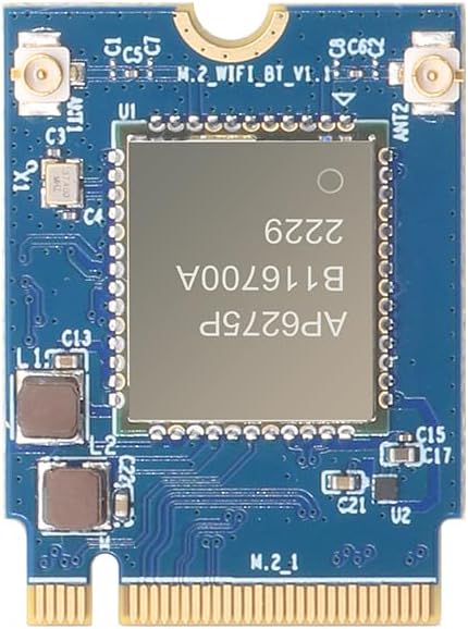
Hold the module against the slot and check the notches line up before pushing. If it does not want to go in, stop. A module that will not seat is the wrong one for the board, not one that needs more force.
Step 2 Seat the module (optional) in the slot
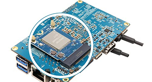
With the board unplugged, turn it over and find the M.2 slot on the underside.
Slide the module in at a shallow angle, roughly 30°, gold contacts first, until it is fully home. Press the free end down and secure it with the small retention screw.
The washer goes between the board and the module, under the free end, not on top of it. The slot holds the contact end of the module up off the board, so the washer is what keeps the other end at the same height. Without it the screw pulls that end down and the module ends up bent and unevenly tensioned rather than sitting flat.
Both the washer and the screw come in the box with the module, so there is nothing to buy for this and nothing to substitute.
Step 3 Connect the antennas
The antenna leads end in small round push-fit connectors. Line one up squarely over its socket on the module and press straight down until it clicks. They seat with very little force and the sockets are delicate, so do not rock or lever them on at an angle.
Step 4 Fit the heatsink fan
Its two pins clip underneath the board, so you want to be able to reach both faces.
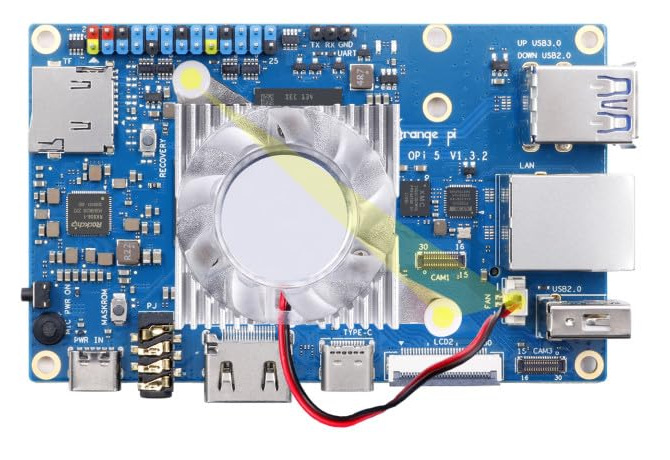
The official heatsink fan sits on the SoC, the large chip in the middle of the board. Check the revision printed on the board before you start: it fits the Orange Pi 5 v1.3.2 and the 5 Plus, and the mounting holes are not in the same place on earlier revisions.
Peel the film off the thermal pad that comes in the box and lay it on the SoC. Sit the heatsink squarely on top with its two tabs over the holes either side, press both spring pins down until they click, and plug the 2-pin lead into the socket marked FAN, which on a v1.3.2 board is between the CAM1 connector and the USB 2.0 port. The pins hold it on, so there are no screws here and nothing to tighten.
This is the Pi's only cooling. Its housing's roof and floor are vented, and nothing else sits over the board inside it.
The finished result
A board that has been prepared: fan on, module in if you are using one, and ready to go into its housing.
Carry on with Orange Pi housing, which closes it into its printed box.