
Helpers — Soldering Pico headers
Soldering Pico headers
How-to guideSoldering 2.54 mm header pins to the Raspberry Pi Pico so it can seat in the control board.
Parts needed
Electronics
- 1×
- 40×
Tools needed
- Soldering iron and solder
- Side cutters or pliers, to break the strip
- A breadboard, or a piece of soft wood and a vice
This step is optional. The parts catalog buys a Pico with its two rows of 20 pins already fitted, so a standard build skips this page. The bare Pico and the 40 header pins listed above are not counted into a machine's parts list, so buy them only if you would rather solder the pins on yourself.
A bare Pico will not seat in the basically Embedded Control Board until 2.54 mm header pins are soldered along both its long edges.
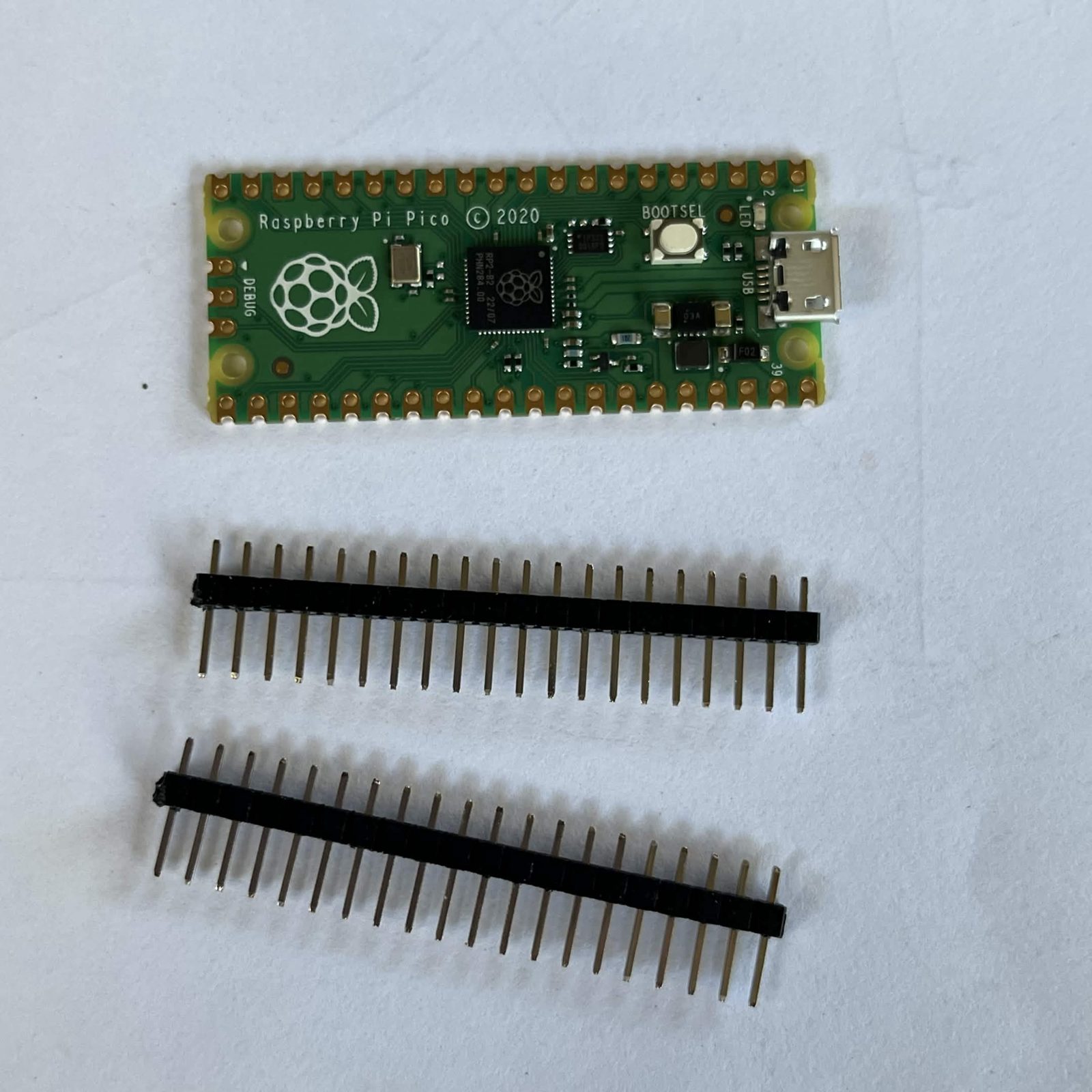
Step 1 Break the strip into two rows of 20
The pins arrive as one long breakaway strip. Break two rows of 20 off it. The strip snaps between any two pins, and side cutters or pliers give a cleaner break than fingers.
Step 2 Fit both rows before you solder anything
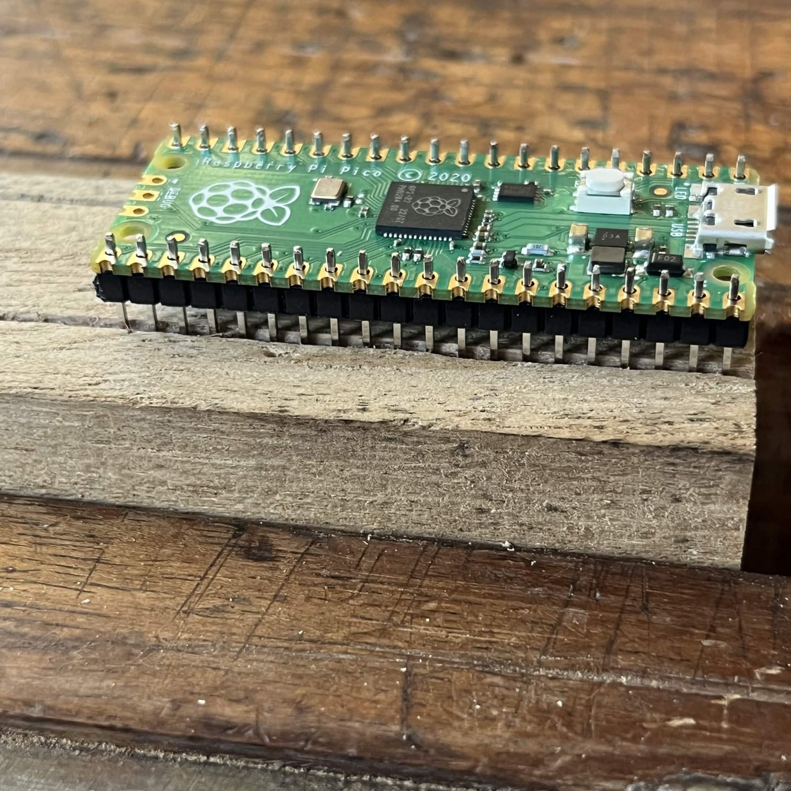
The pins point away from the chip side, the side with the black chip, the USB socket and the button. The plastic of each row sits flat against the other face, and you solder on the chip side. Undoing this means desoldering forty pins.
Push both rows of 20 into the Pico, long ends down, until the plastic sits flat against the board. Both rows go in now, before the iron touches anything: solder one row on its own and the second one has to follow whatever angle the first one set, and the Pico will not sit flat in the control board.
Step 3 Stand the pins in something that holds them square
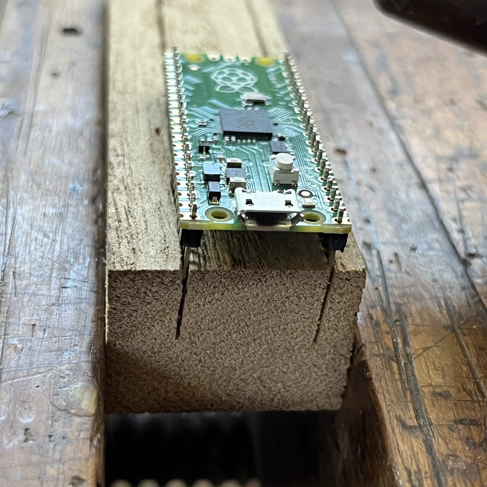
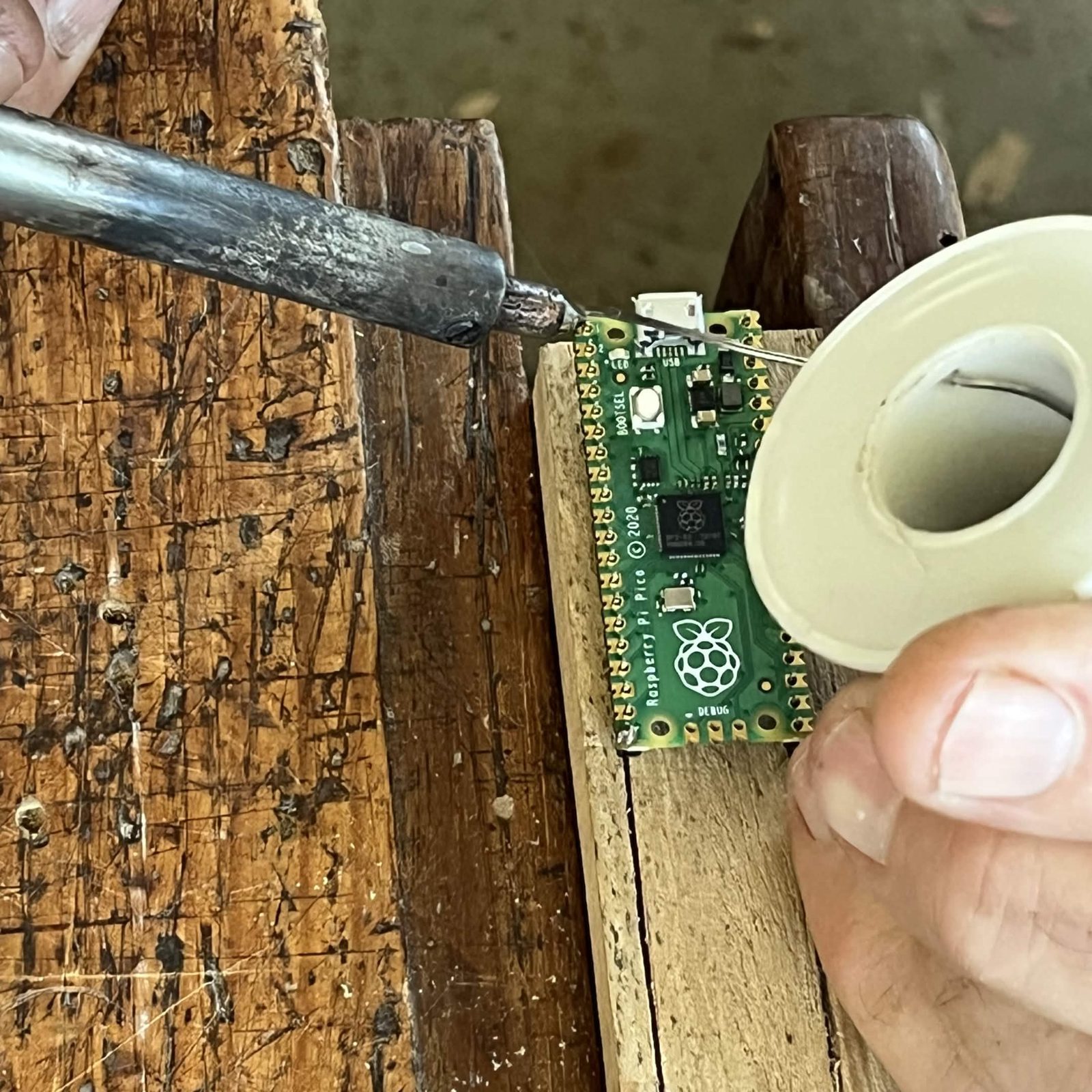
A breadboard does this if you have one. If you do not, two saw cuts in a piece of soft wood do the same job: cut them 17.8 mm (0.7 in) apart, which is the spacing of the Pico's two rows, drop the pins into the cuts and hold the wood in a vice. The Pico sits flat on the wood with both of your hands free.
Step 4 Solder the four corners, then the rest
Set the iron to around 350C (660F), or 320C (610F) if your solder is leaded.
Getting clean joints. Use the parts straight out of the packet: dust and finger oil on the pins or the pads fight the solder. Flux-cored solder carries enough flux on its own, so if you add any extra, add a little. Heat the pin and the pad together until the solder runs into the hole on its own, then take the iron off. Solder that has to be pushed into place was too cold, and an iron parked on a pin softens the black plastic that is holding the row square.
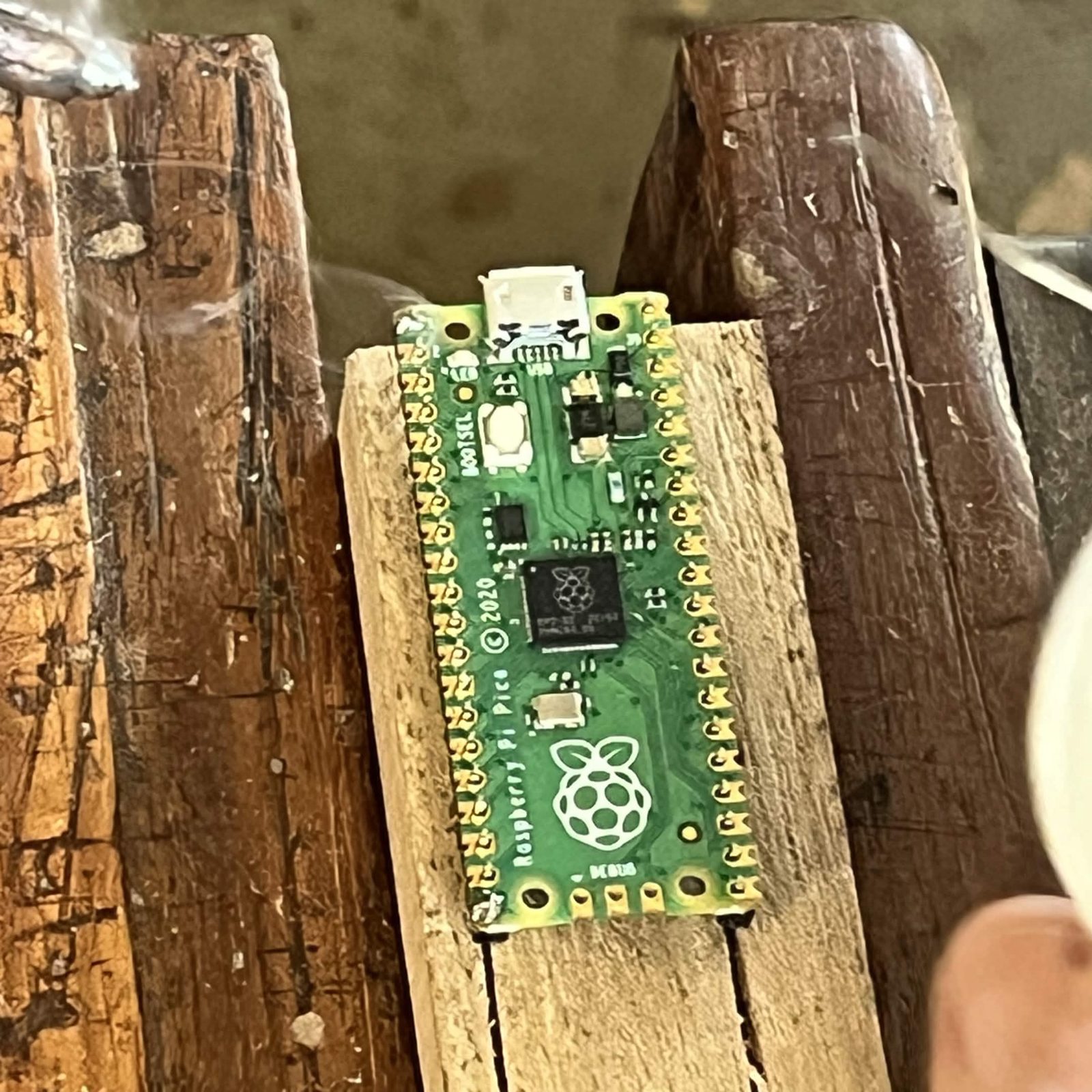
Solder one pin at each end of both rows, four joints in total. Then look along the board: if a row leans, or a plastic body has lifted off the Pico, reheat that corner and press it down before going further. Then solder the remaining 36.
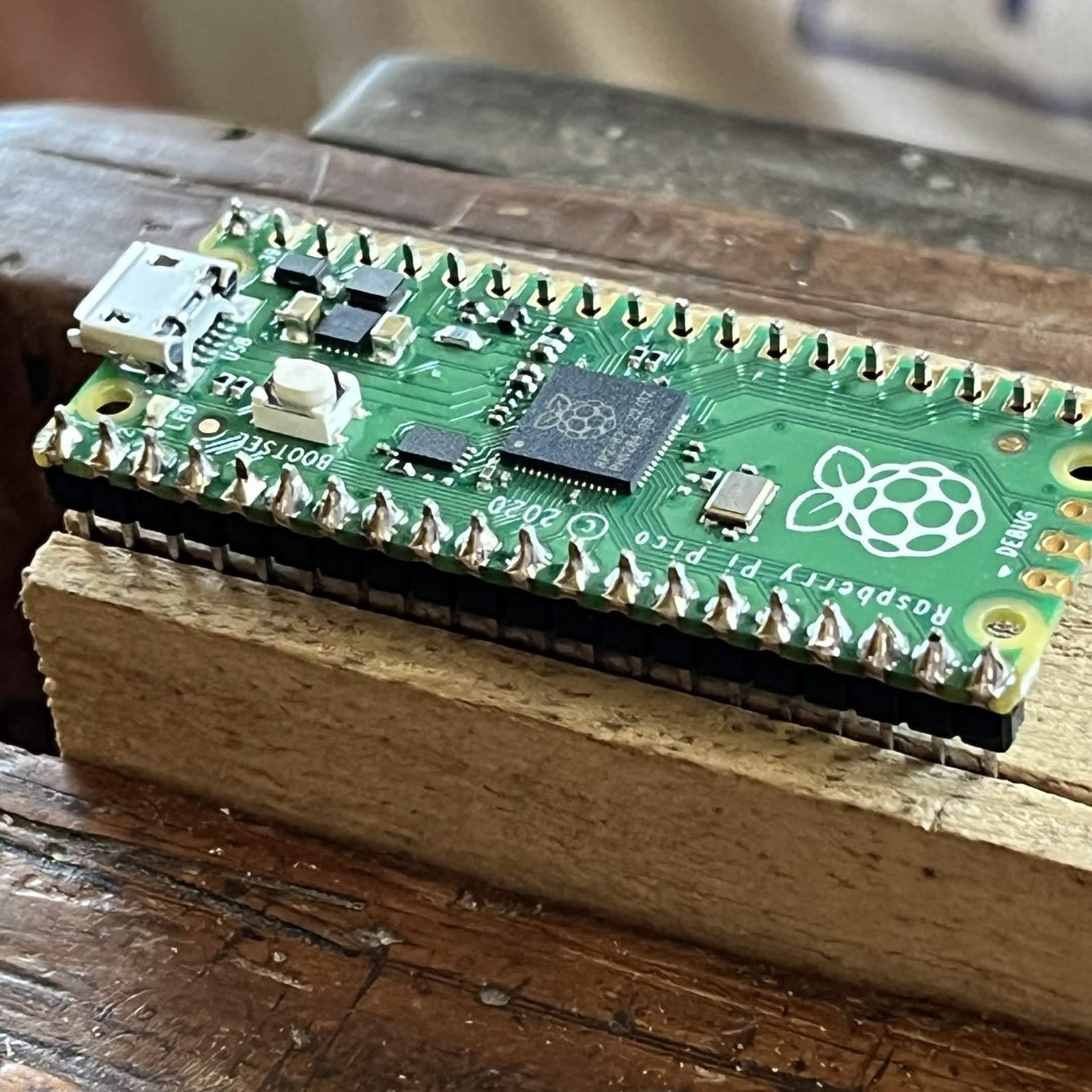
The finished result
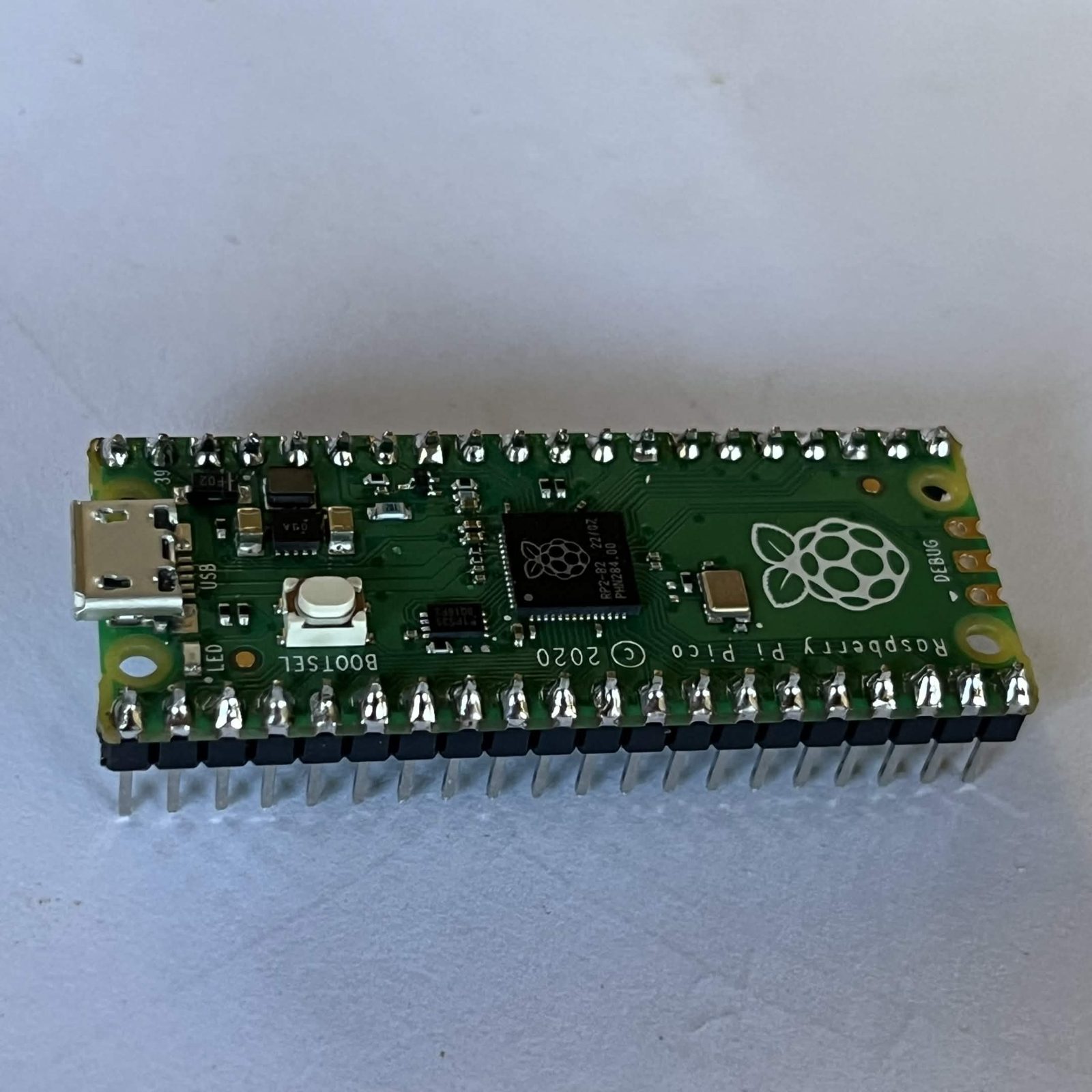
A Pico with two rows of 20 pins soldered on, pointing away from the chip side.
It goes into its sockets in step 2 of preparing the control board. Flashing the firmware is covered in software setup.