
Distribution — Stacking the layers
Stacking the layers
How-to guideJoining the finished layers and the top interface into the standing frame.
Parts needed
Screws
- 12× 16mm
A an interchangeable alternative works (hover for what).
Tools needed
- Hex key, 3 mm for a button head or 4 mm for a socket head
Every layer of the bin frame is built flat, on its own, and none of the pages that build them says how they go together. This one does. At the end of it the frame is standing and empty, ready for the chutes to go in.
Those screws are the only loose parts this page uses, and the quantity above is for one joint. An N-layer machine has N joints, because the top interface's own frame lands on the stack the same way a layer does, so the whole job takes 12 × N of them: 36 at three layers, 60 at five. Everything else is already fitted to the layers you are joining.
Elements needed
Every one of these is built on another page. Have them all finished before you start, for an N-layer machine.
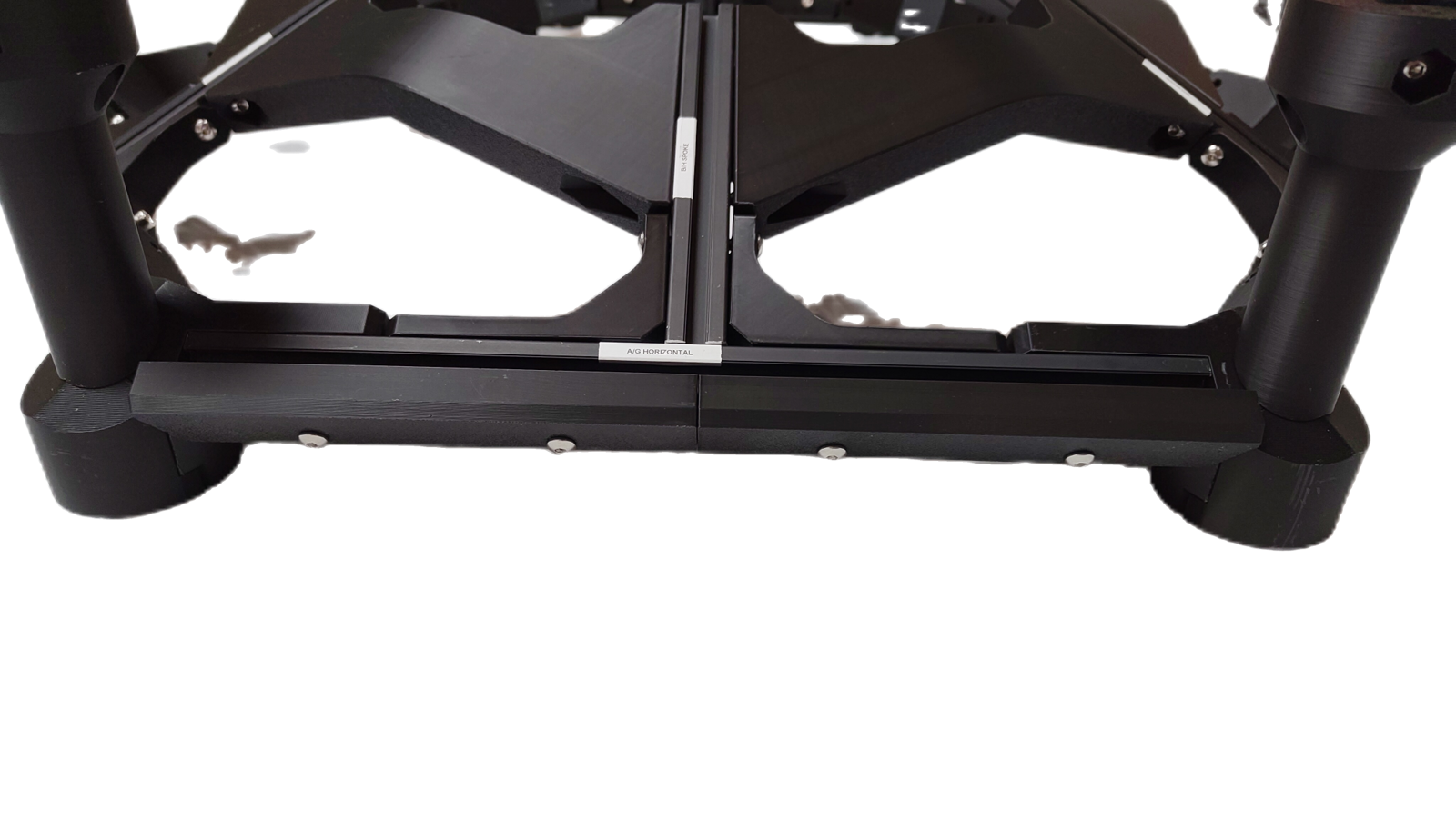
1 × bottom layer, standing on its six casters. It is the base of the stack and the only layer that does not land on another one.
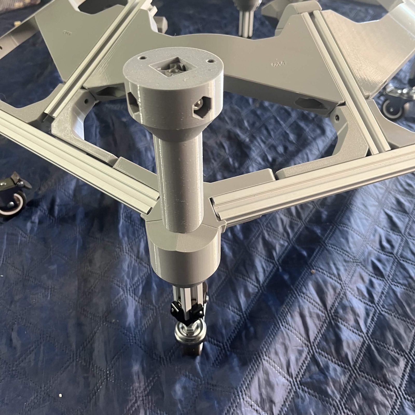
N−1 × regular layers, every bin layer above the lowest. Each one carries the vertical and the bracket that reach up to the layer above it.
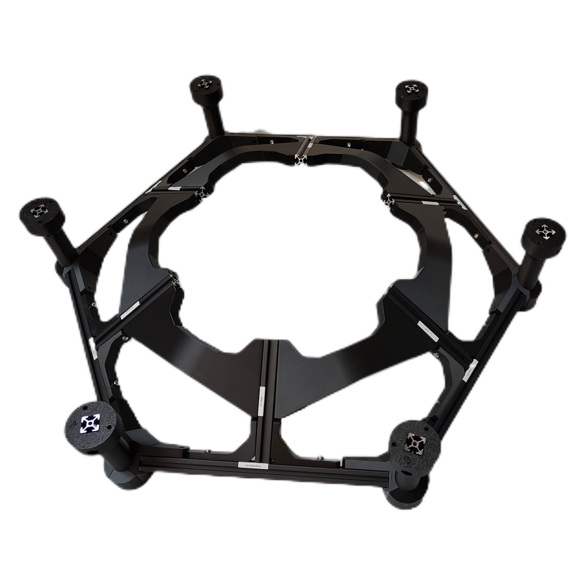
N × sets of bin retainers, twelve on every layer including the bottom one. Fit them while the layer is still something you can turn around, not once it is on the stack.
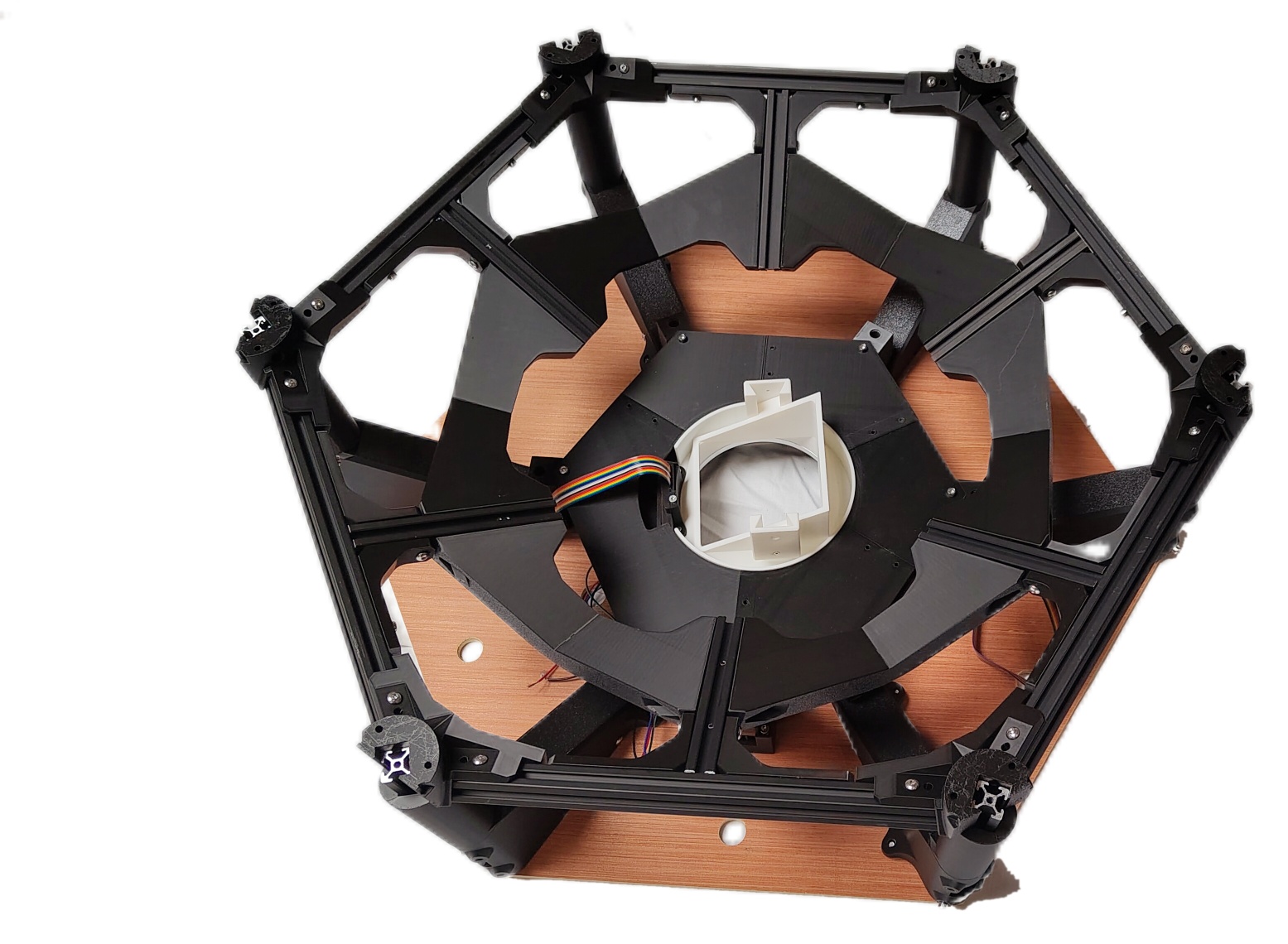
1 × top interface, its own hex frame included. That frame lands on the top bin layer through the same joint every other layer uses, which is why it counts as one of the N joints.
The chutes and the bottom interface are not needed yet and must not go in while you stack.
Fastener icons match the parts list: the silhouette is the head shape, the colour is the thread size. M3 M4 M5 M6
Step 1 Decide which way up to build
There are two ways to do this and the machine comes out the same either way.
Upside down: the top interface goes on the bench with its top plate down, then each layer is added onto it in turn, and the bottom layer with its casters goes on last. The whole stack is then turned over onto its wheels. At every joint the 12 screws go in from above, straight down into a joint you can see, instead of overhead underneath a tower that is already taller than you.
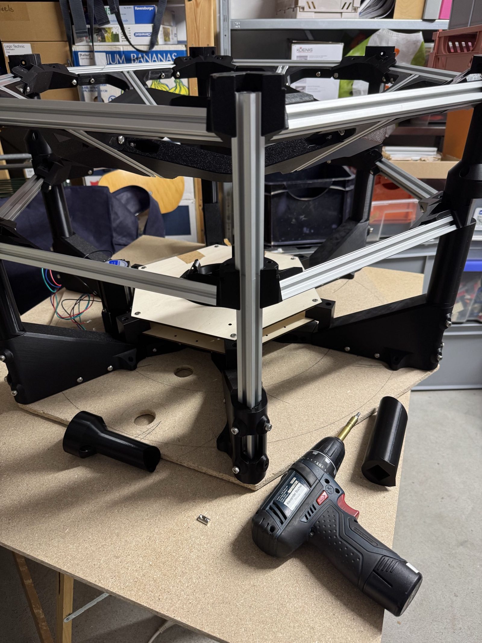
The right way up starts from the bottom layer on its casters and works upward, capping the stack with the top interface. It matches the order the pages are written in and needs no flip at the end, but every joint is driven overhead and the tower gets tall quickly.
Whichever you pick, the joint itself is identical. The whole frame goes together before any chute does.
Step 2 Join one layer to the next
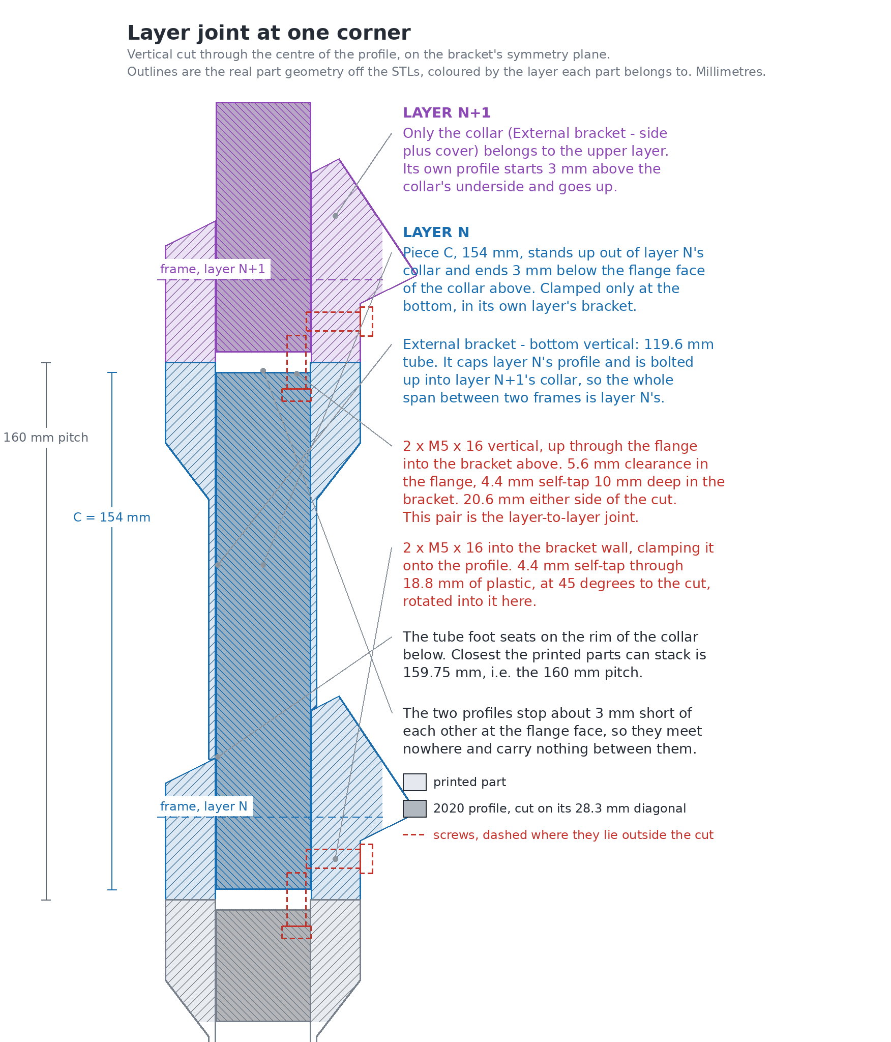
A finished layer already carries everything that spans up to the next one: its vertical extrusion standing out of the External bracket — side, and the External bracket — bottom vertical capping that extrusion. Joining two layers is therefore only the flange joint at each of the six corners.
Set the next layer down so that each External bracket — bottom vertical's flange face meets the underside of that layer's External bracket — side, and drive 2 M5 × 16 mm socket / button head screws up through each flange into the bracket above. That pair is the whole layer-to-layer fastening, 12 screws per joint.
The numbers on the drawing:
- External bracket — side and cover, the 60.5 mm collar at each frame.
- Piece C, 154 mm cut. It starts 3 mm above its own collar's underside and ends 3 mm below the flange face of the collar above, so it spans the whole 160 mm between one frame and the next. At the bottom joint this is piece D instead, which is the same span plus the leg.
- External bracket — bottom vertical, 119.6 mm of tube. It sleeves the upper part of the extrusion, so it is not visible on an assembled machine, and its foot seats on the rim of its own layer's collar. That seat is what sets the 160 mm spacing between frames.
- The two M5 × 16 mm socket / button head screws that join the layers, up through the flange into the bracket above. Use the 16 mm, not a longer one.
- The two M5 × 16 mm socket / button head screws that clamp the bracket onto the extrusion, self-tapping through the bracket wall. The extrusion is held only here, in its own layer's bracket, and nothing screws into it from the layer above.
- Where two extrusions meet: they stop about 3 mm short of each other at the flange face and never touch.
The joint is the same at every level, including where the first regular layer lands on the bottom layer, and where the top interface's own hex frame lands on the topmost bin layer. There is no special case anywhere in the stack.
Step 3 Work through the whole stack
Repeat step 2 until every layer is on and the top interface is at the top of the tower. Building upside down that means starting with the interface and finishing with the bottom layer; the right way up it means the reverse.
Nothing else is fastened between layers. The layers do not interlock with each other through the extrusion: the 12 screws at each joint are the only thing holding one layer to the next, which is worth knowing before you go looking for a fixing you have missed.
The finished result
Every layer on, twelve screws at each joint, the top interface at the top of the tower and nothing inside it.
The frame is now standing and empty. The chutes go in next, one at a time and without their funnels, and the bottom interface goes on after them, because its bearing carries the bottom of the chute stack. Both are on the Chute page.
The Distribution page contains the instructions for the entire assembly, and is where you should return once you're done here.