
Helpers — LED strips (L1 to L3, L1p to L3p)
Preparing the LED strips (L1 to L3, L1p to L3p)
How-to guideOne machine needs three LED strips. This page describes how to cut a length of 24 V strip and make the cable that takes it to the control board (L1 to L3, L1p to L3p), with an optional but recommended barrel plug and socket where the lamp comes off.
Parts needed
Wire harness
- 1×About 920 mm of 24 V strip cut from a 5 m roll. One roll does all three lamps.
- 3×One per lamp. Strip in one end, your wire in the other.
- 3×Recommended. One per lamp, on the pigtail.
- 3×Recommended. The unplug point in an LED drop, on the board cable.
- 8×Two per lamp, one for each wire of the barrel socket, and two on each of the control board's and the Orange Pi's 24 V leads. Six more are spares.
- 3×Cut the male end off and join the barrel socket to it.
- 1×Optional. About 1 m (39 in) over each of the three board cables (L1 to L3) and 100 mm (4 in) over each of the three lamp pigtails (L1p to L3p).
A an interchangeable alternative works (hover for what).
Tools needed
- Side cutters
- Wire strippers
- Multimeter (only if you fit the plug and socket)
- Insulated-terminal crimping pliers with a die for 22 to 16 AWG (0.33 to 1.3 mm²) wire, for the butt connectors
- Only if you solder instead of crimping or clamping: a soldering iron, solder and 3 mm (0.12 in) adhesive-lined heat shrink (see Getting started)
- Only if you make your own Dupont cable: a crimp tool for open-barrel contacts
- Optional, for the sleeving: scissors and tape, or a hot knife
Each camera lamp needs a cable that takes 24 V from the control board to its strip. The best way to build it is two cables that meet at a barrel plug and socket: the board cable (L1 to L3) and the lamp pigtail (L1p to L3p). The plug and socket are optional but recommended. They make maintenance easier: the power supply to a lamp can be disconnected right next to the lamp, so you can take a lamp down, swap it or work on it without touching the board end of its cable or the cables of the other lamps. A machine takes three of each. The quantities above are a whole machine's worth: one 5 m (16 ft) roll cuts into five lengths, and the Dupont cables come five to a pack.
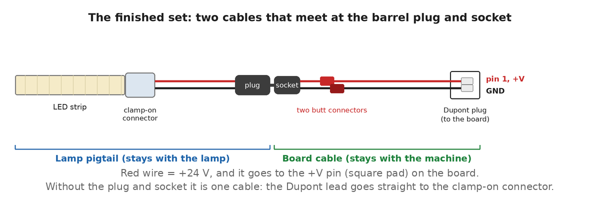
L1p to L3p) stays with the lamp, the board cable (L1 to L3) stays with the machine.Pick your build:
- Plug and socket: fit them (recommended), or leave them out. Leaving them out makes one cable: skip steps 3 and 5, and the Dupont cable's cut end goes onto the strip in step 4.
- Strip end: clamp it with a connector (step 4).
- Socket joints: crimp them with butt connectors (step 5).
Nothing here needs soldering. If you would rather solder a joint, the connector cards in the parts list name it as the alternative.
Check the roll you bought is the 24 V one. The board's LED headers feed 24 V.
The socket goes on the board cable (L1 to L3) and the plug goes on the lamp pigtail (L1p to L3p), never the other way round. The board end is live at 24 V whenever the power supply is on, and a socket has its contacts recessed where a plug's are not. Both are 5.5 x 2.1 mm (0.217 x 0.083 in), centre-positive: the tip is +24 V and the sleeve is ground.
Step 1 Cut the strip to length, on a mark
Two turns of the camera lamp's reflector skirt, which is about 920 mm (36 in) of strip. One 5 m roll gives five lamps' worth.
Take off any wire the roll came with. Some rolls have a wire soldered to the end, and it may finish in a female connector. Cut the strip just past its solder joints, on a mark, so the wire and its connector go and the strip starts with bare pads. Measure from there.
Cut only on the printed marks, never between them: the solder pads are at the marks, so a cut anywhere else leaves nothing to connect to. The marks are not the same pitch on every roll, so count marks rather than millimetres: coil the strip dry inside the skirt and cut at the last mark before the free end reaches the start of the coil. That lands somewhere near 920 mm (36 in).
Take the mark under two turns rather than the one over it. Strip past two turns has nowhere to sit: it lifts out from under the cover and the light leaves the lamp at an odd angle. A small gap where the ends do not quite meet does not show.
Leave the blue protective film on until the strip is going where it lives. It is the only thing keeping grease off the adhesive.
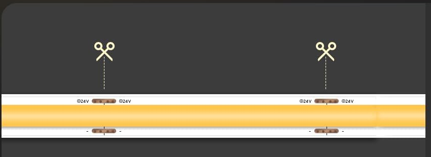
+24V on one side. Manufacturer diagram (VOEWT).
Step 2
Cut the male plug off the Dupont cable (L1 to L3)
The cable comes from the pack with a plug on both ends: the male one has two pins sticking out of it, the female one has two holes. Cut the male plug off. The female end stays on: that is what pushes onto the board later. With the plug and socket, the socket joins here in step 5. Without them, this cut end goes straight onto the strip in step 4, and you skip steps 3 and 5.
If you own a crimp tool for open-barrel contacts, you can make this cable instead: about 920 mm (36 in) of 22 AWG (0.33 mm²), one red and one black, with a 2-pin 2.54 mm (0.1 in) Dupont female housing crimped on (how is at Crimping connectors). Put the black wire's contact in the cavity next to the moulded arrow, so the arrow marks ground on the cables you make.
The housing has no key, so it pushes onto the board's two pins either way up. The arrow moulded into it always marks the black (ground) wire. Fit the housing with the arrow end over the pin the board prints GND, the round pad, and the red wire is then over +V on the square pad. The ready-made cables in the listing photo have the arrow beside the black wire's contact too, so one rule covers both. If you do get it the wrong way round, nothing is damaged: the LEDs simply will not light, so turn the housing half a turn.
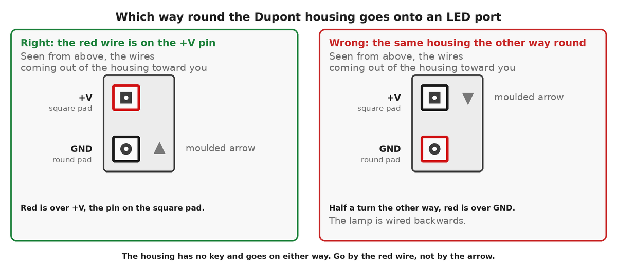
GND. Wrong: turned half a turn, with the arrow end over +V.Optional: if you will sleeve the board cable (L1 to L3), slide a 1 m (39 in) length of braided sleeving over its two wires from the cut end now, before you join the socket in step 5 or clamp the wires onto the strip in step 4. A finished socket or clamp may not go through it, so it goes on first. If you make your own cable, slide it on before you crimp the housing. Sleeving (optional) says how to cut and finish it.
Step 3 Find the tip of the plug and of the socket
Only if you are fitting the plug and socket. Set the multimeter to continuity and hold one probe on the centre pin. The wire that beeps is the tip, which is +24 V. The other is ground. Do this for the plug and for the socket, and do not go by wire colour, because moulded plugs are not consistent about it.
Then cut the plug's wires, which make the lamp pigtail (L1p to L3p), to about 150 mm (6 in).
Optional: if you will sleeve the lamp pigtail (L1p to L3p), slide a 100 mm (4 in) length of braided sleeving over its two wires from the cut end now, before you clamp them onto the strip in step 4.
Step 4 Clamp the wires onto the strip
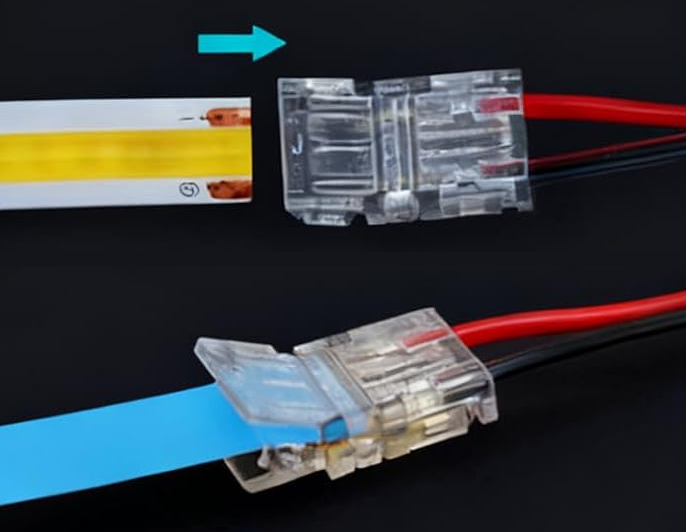
The solderless connector is a hinged body with sprung contacts at each end: the strip goes in one end, the wire in the other, and nothing is stripped or tinned.
- Lift the lid at the strip end, slide the cut end in until the two copper pads sit under the contacts, and press it shut.
- Clamp the plug's two wires into the other end (or, without the plug, the Dupont cable's two wires). The tip wire (or the red wire) goes on the
+24Vside. It bites through the insulation, so the wires do not need stripping either. The connector is made for 22 AWG (0.33 mm²) wire, so check your plug's leads are about that size, and tug each wire once the lid is shut.
Match the width. These are 8 mm (0.31 in) COB connectors and nothing else will grip: a 10 mm (0.39 in) body, or one meant for SMD strip, will not hold the pads against the contacts. Buy SBL-RA2P-8: the -DC variant ends in a barrel socket, which is the wrong way round on the lamp pigtail (L1p to L3p).
Step 5
Crimp the socket's wires to the cable (L1 to L3)
Only if you are fitting the plug and socket. The socket's wires and the Dupont cable's wires are joined end to end, one joint per wire, so there are two. The socket's tip wire joins the cable's red wire, and the socket's ground wire joins the black one. Red is the wire that goes to +V on the board, so this is the joint that keeps the polarity right. Do one joint at a time so the two never touch.
A butt connector is a vinyl-insulated barrel that takes one wire in each end, rated for 22 to 16 AWG (0.33 to 1.3 mm²) wire. Nothing is soldered. Three lamps need six; the list has eight, two for a crimp that goes wrong. More on crimping is at Crimping connectors.
- Strip 7 mm (0.28 in) off both wires of each joint, and twist the strands of each wire tight.
- Push the socket's wire into one end of a red butt connector, and the cable's wire of the same colour into the other, until the insulation of each wire meets the end of the barrel.
- Close each end of the barrel in the die of the insulated-terminal crimping pliers marked for 22 to 16 AWG (0.33 to 1.3 mm²), so each wire is crimped separately. Squeeze until the tool releases. Pull on each wire to check it holds.
- Stagger the two butt connectors by a few millimetres along the cable so they cannot touch.
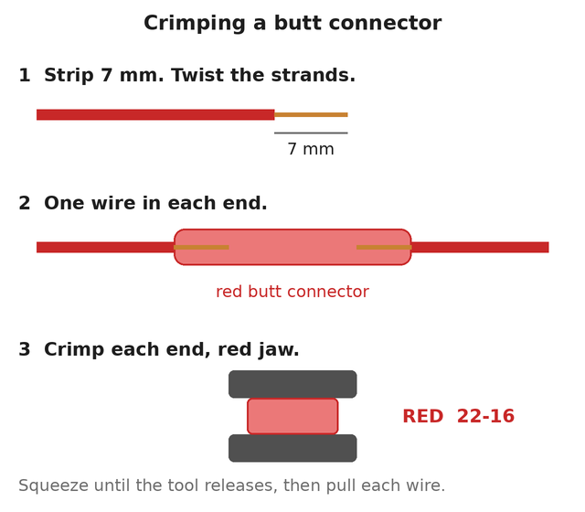
Use insulated-terminal crimping pliers. A crimp tool for open-barrel contacts, the kind that does Dupont and PH, has the wrong die and will not close a butt connector properly.
Step 6 Check it before it goes anywhere
Set the multimeter to continuity. With the plug and socket, push the two cables together first.
- Touch one probe to the strip's
+24Vpad and the other to the hole in the Dupont housing that the red wire runs to. It should beep. That is the contact that goes over+Von the board. - Move the second probe to the other hole in the housing. It should not beep.
- Put one probe in each of the two holes. It should not beep.
If the first test does not beep, or the second does, the two joints have crossed. If the third beeps, something is shorting.
Sleeving (optional)
You can skip this and the lamp works the same. The sleeving is on the parts list as optional. It keeps the two wires together as one tidy cable and protects them where the cable runs along the frame, and it is another way of securing the cables.
Where: over the two wires of each board cable (L1 to L3), from just short of the barrel socket (or of its butt connectors) to just short of the Dupont housing, about 1 m (39 in). The short lamp pigtail (L1p to L3p) can have a 100 mm (4 in) length as well, from just short of the clamp to just short of the plug. Three of each per machine.
How:
- Push the braid together lengthwise to open it: it widens as it shortens. Feed both wires into it together, so neither is left outside.
- Cut it to length with a hot knife or a soldering iron with a blade tip, so the cut melts shut. Plain scissors leave the braid fraying. With no hot tool, wrap a turn of tape around the braid where you will cut, cut through the middle of the tape with scissors, and leave the tape on.
- Stop the sleeving 5 to 10 mm (0.2 to 0.4 in) short of the socket, the plug, the clamp and the Dupont housing, so the sleeving never crowds into them and the joints can flex.
- Hold each end with a small piece of heat shrink or a turn of tape, so that the braid cannot creep back along the wires.
The finished result
With the pair fitted, two cables that plug together. A two-turn length of strip, about 920 mm (36 in), with its male barrel plug on the end of a short pair of wires (the lamp pigtail, L1p to L3p), and 1 m (39 in) of red and black wire with a female barrel socket at one end and a 2-pin Dupont plug at the other (the board cable, L1 to L3). Three of each make a machine. Without the pair it is one cable, the Dupont cable running straight to the strip. Nothing is joined end to end along the strip, so its far end stays dead.
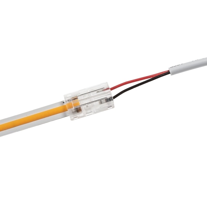
The Dupont end goes onto an LED port at connecting the components, step 4.