
Helpers — Cable cage plates
Preparing the 3D printed cable cage plates
How-to guideGluing the printed cable cage pieces into the two hexagonal plates, as an alternative to laser-cut ones.
Parts needed
Printed parts
- 10×
- 1×
Screws
- 12× 12mmOnly a temporary clamp while the glue sets. They come out again.
Nuts
- 12×Only a temporary clamp while the glue sets. They come out again.
A an interchangeable alternative works (hover for what).
Tools needed
- Superglue (cyanoacrylate)
- A flat surface to build the plate on
- A 2.5 mm hex key, for the M3 bolts
- A file or sandpaper, for any hard glue
This page is optional. The standard build has both cable cage plates laser-cut, or cut by hand from the parts calculator's laser-cut page. If you would rather print them, this page turns the printed pieces into the same two plates, and the top interface page takes it from there.
Each plate is made of several flat pieces. Where two pieces meet, each has a half-thickness step, and the two steps overlap. Two M3 holes go through every overlap. Ten hex corners and one motor piece make both plates:
- The plate with the plain round centre hole is six hex corners. It is the one that goes on at step 10 of the top interface page.
- The plate with the keyed cutout is four hex corners and the one motor piece. The motor piece is the one with the pocket in its edge. It goes on at step 12.
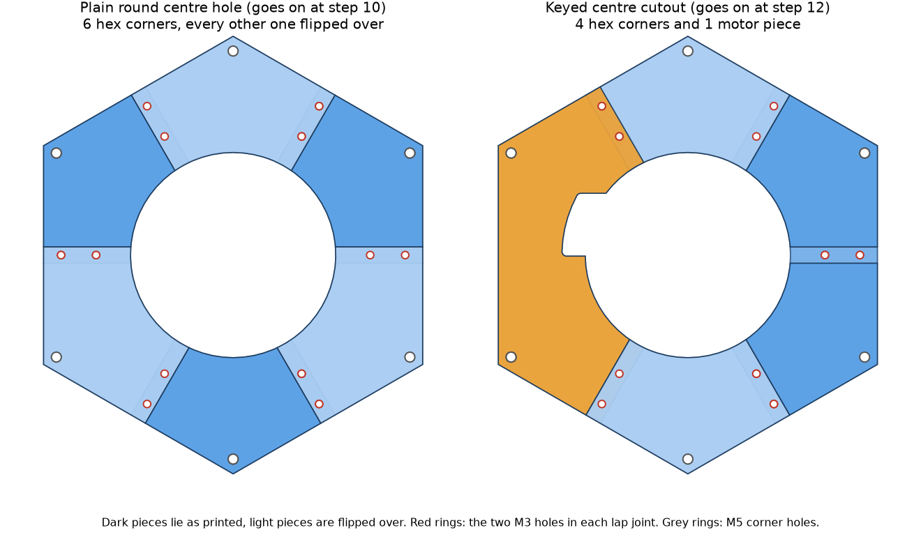
Print the pieces in PLA, with the Print settings at the top of the parts calculator. Print every piece flat on the bed, the way the file comes.
Step 1 Dry-fit the plate
Lay the pieces on a flat surface in the order in the drawing above, with every other corner piece turned upside down. At each overlap one piece has its step on the underside and the next has its step on the top. If an overlap does not lie flat, turn one of the two pieces over.
Step 2 Clamp the joints with M3 bolts
Put an M3 × 12 mm socket / button head bolt through each of the two M3 holes in every joint, with an M3 nut on the back, and tighten them by hand until the pieces lie flat. That is two bolts per joint, so 12 for the six-piece plate and 10 for the five-piece one, and the same bolts go on the second plate once the first is done.
The bolts are only a clamp. They come out again in step 4. Do not overtighten them: the plate must stay flat.
Step 3 Glue every joint
With the plate flat and the bolts in, put superglue between the two steps of every overlap, then press them together. Keep the plate flat on the table. Leave it for the full curing time on the glue's label before you lift it.
Step 4 Take the M3 hardware out
Once the glue has cured, take every bolt and nut out. Leave nothing in the plate: the ribbon cable runs through the cage, and a bolt or nut left on the plate catches it as the chute turns. Run a fingertip over both faces of every overlap, and file or sand any hard glue flat.
Do the other plate the same way.
Check the plate before it goes on
Look at the central hole of the finished plate. The edge must be smooth all the way round, with no step or lump of glue at any overlap, because the chute turns inside it.
Where it goes
The plate with the plain round hole goes on at step 10 of the top interface page, and the plate with the keyed cutout at step 12. Nothing else about the cage changes.