
Distribution — Top interface
Top interface
How-to guideThe interface between the feeder and the bin tower.
Parts needed
Printed parts
- 1×
- 5×
- 1×
- 6×
- 6×
- 1×
- 1×
- 1×
- 1×
- 1×
- 1×
- 1×
- 1×
- 1×
- 1×
- 1×
- 1×
- 5×
- 1×
- 1×
- 1×
- 1×
Laser-cut parts
Cable cage plates: laser cut or 3D printed
Laser cut
- 1×
- 1×
3D printed
- 10×
- 1×
- 1×The machine's hexagonal top plate; the interface mounts under it.
Aluminum extrusion (2020)
- 6× 238mm2020 aluminum extrusion, cut to 238 mm (piece E).
- 6× 274mm2020 aluminum extrusion, cut to 274 mm (piece F).
Bearings
- 1×
- 1×
Motors
- 1×
Pulleys
- 1×
Wire harness
- 1×
Electronics
- 1× 1.2m
Heat inserts
- 16×
- 8×
- 24×
Screws
- 1× 6mm
- 9× 8mm
- 3× 12mm
- 6× 12mm
- 2× 16mm
- 1× 20mm
- 1× 40mm
- 8× 16mm
- 6× 8mm
- 4× 12mm
- 50× 16mm
- 24× 20mm
- 14× 22mm
- 6× 30mm
- 6× 35mm
Nuts
- 1×
- 56×
- 6×
A an interchangeable alternative works (hover for what).
Tools needed
- Hex keys, 2 mm, 2.5 mm, 3 mm and 4 mm
- Spanner, 8 mm, for the M5 nuts
- Soldering iron or heat-set insert press
The top interface holds a chute that rotates on a lazy-susan bearing to aim incoming parts at whichever bin layer is currently selected. A NEMA 23 stepper drives the rotation through a small gear train (steps 6 and 9), and a limit switch and hammer (steps 4, 6, 8) give it a fixed reference point to home against, since the stepper alone has no way to know which way it is pointed. Everything on this page bolts onto the Top plate, which then sits on the hex frame built on the bin-frame page.
Have a hex frame ready by step 13. It's a required component of this page — step 13 places one onto the assembly, it doesn't build one. The rest of this page (steps 1-12, 14+) doesn't need it.
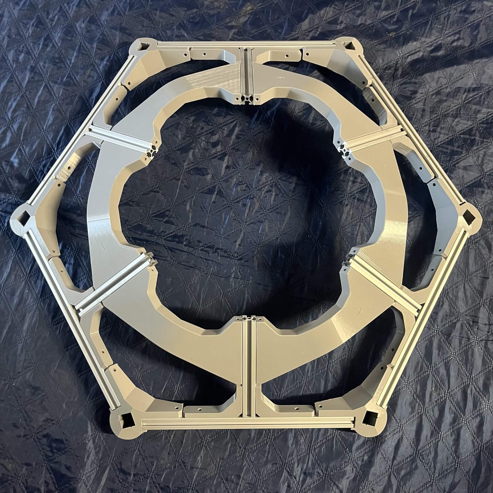
Have the Top plate laser-cut and ready by step 2. It's not printed or built on any page, it's ordered or hand-cut ahead of time — see the parts calculator's lasercut page for the DXF and hand-cut instructions.
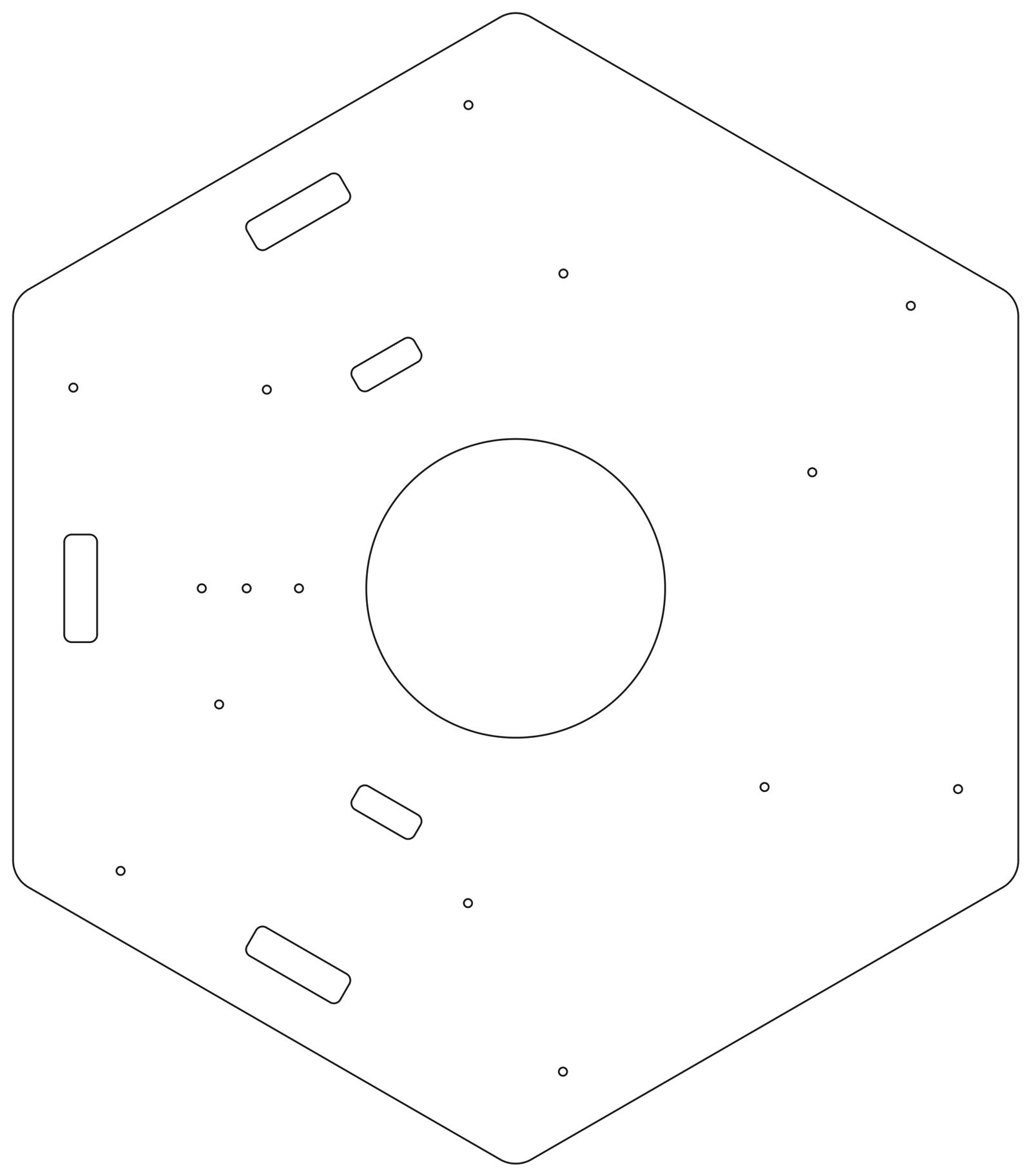
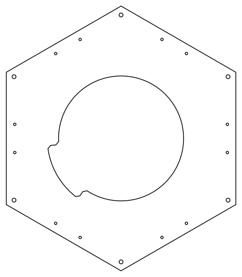
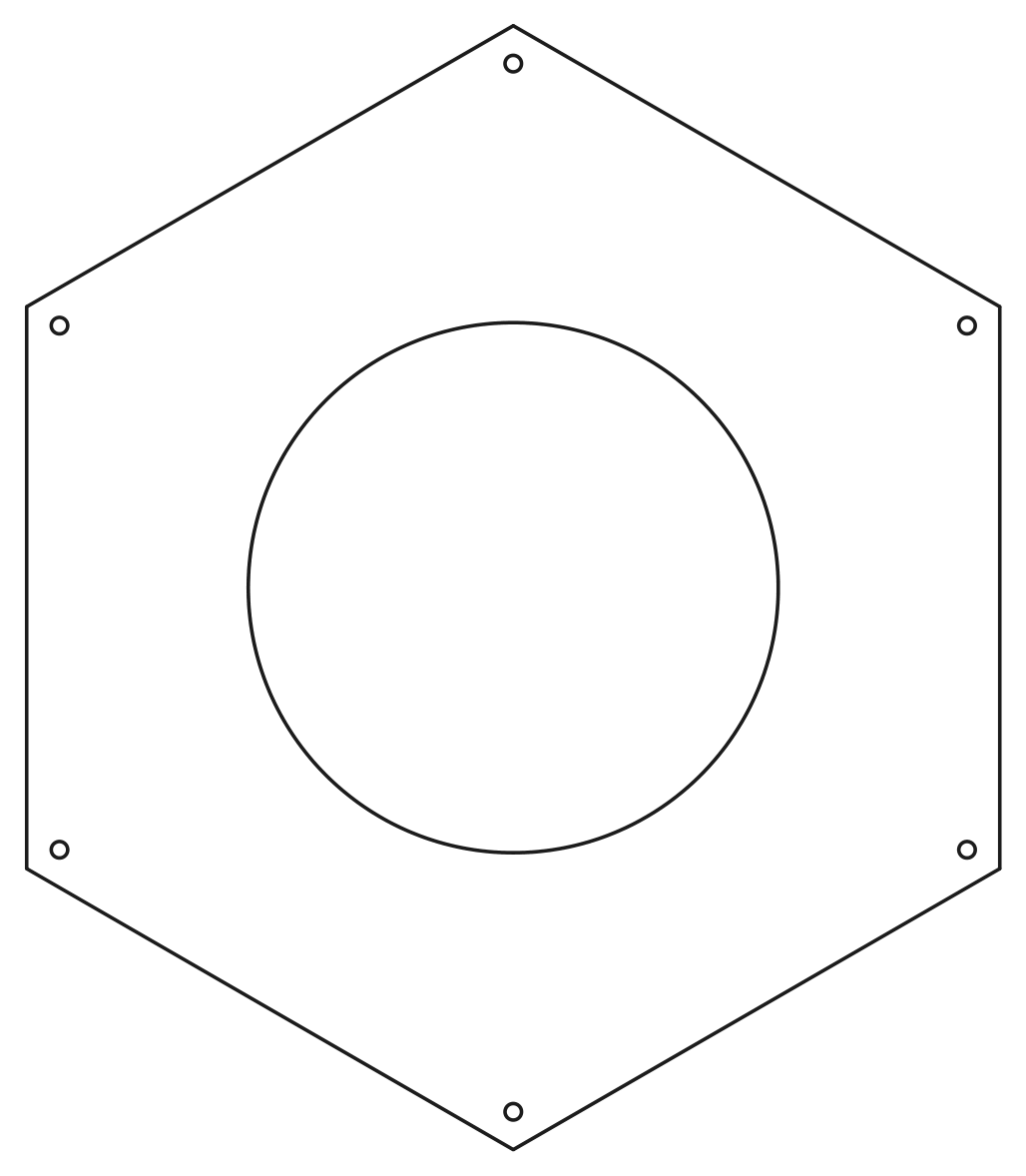
Have the Cable cage top laser-cut and ready by step 10, and the Cable cage bottom by step 12. Same as the Top plate: laser-cut ahead of time, not built on this page.
Printing the cable cage plates instead? The parts list offers two options: the two laser-cut plates, or ten printed hex corners and one printed motor piece. For the printed ones, glue the pieces into the two plates first, on Preparing the 3D printed cable cage plates, and have them ready by step 10 and step 12. The steps below are the same either way.
The fasteners and quantities are in the parts list above and are called out inline at each step.
Fastener icons match the parts list: the silhouette is the head shape, the colour is the thread size. M3 M4 M5 M6
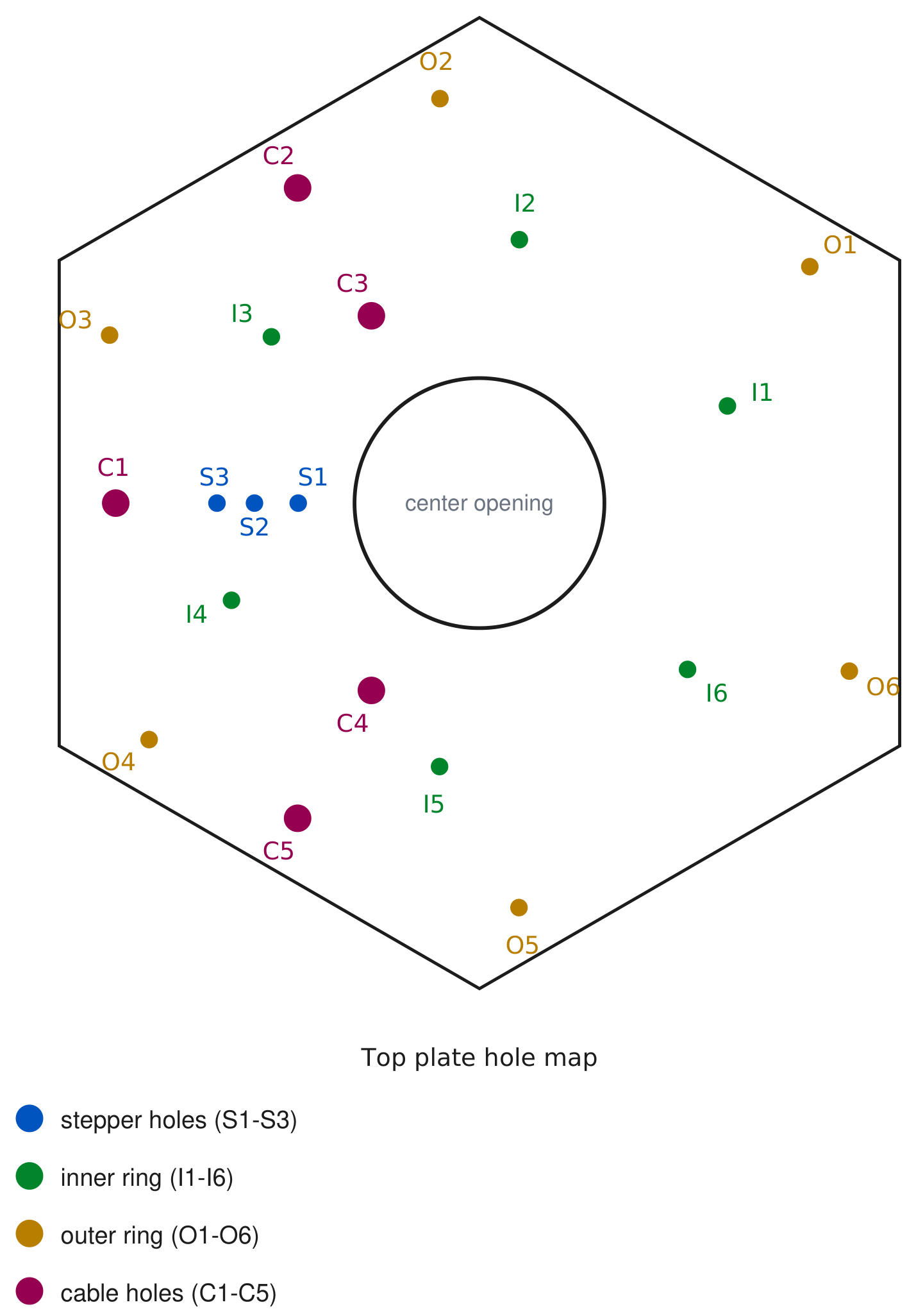
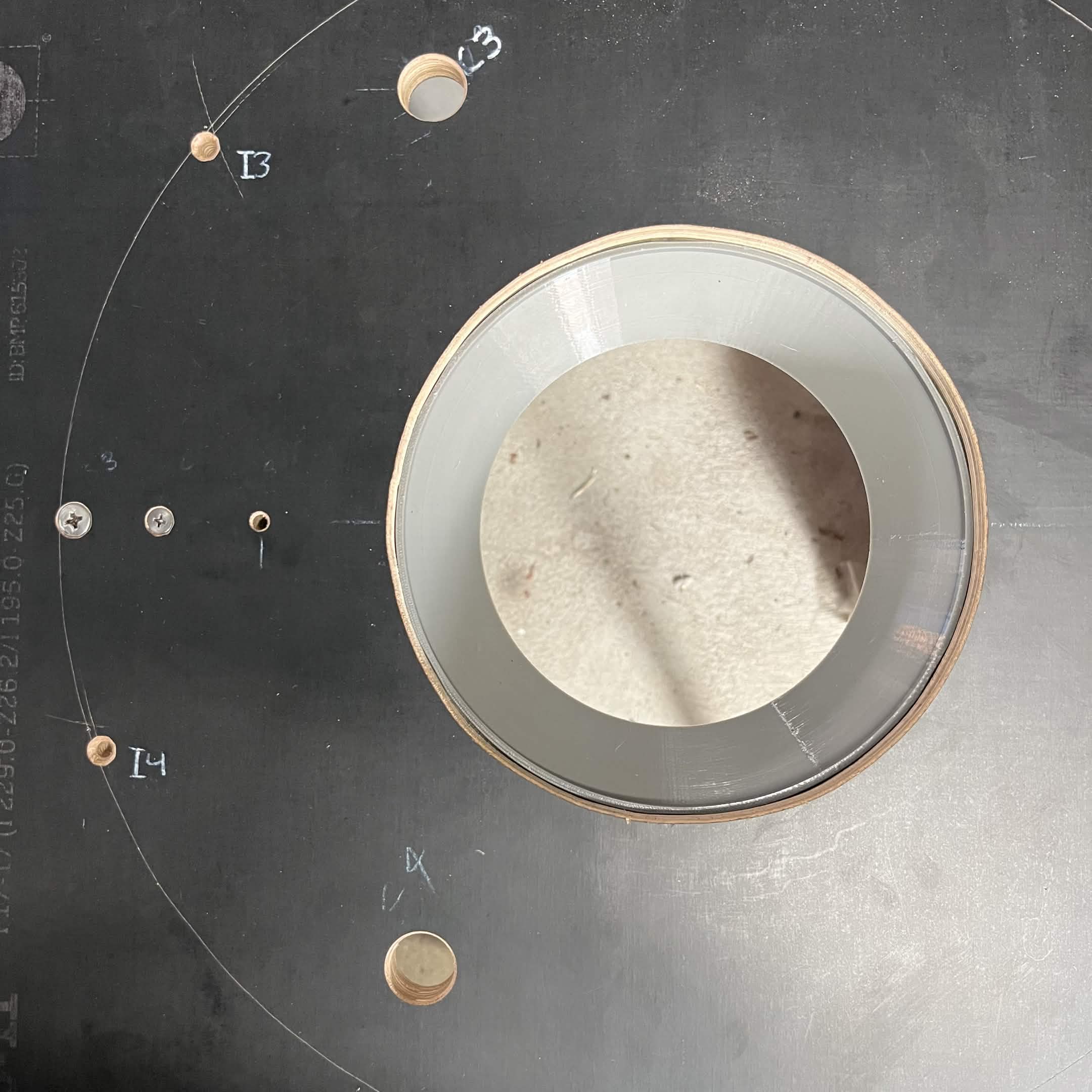
Several steps below refer to holes in the Top plate by name (S2 and S3 for the stepper mount, I1 to I6 and O1 to O6 for the interface brackets). This map shows which hole is which:
Step 1 Preparation
Before assembling anything, press all the heat inserts listed below into their parts while the parts are still loose — this covers every insert used on this page. Fusing them in afterwards is much harder, for example once the Interface upper fixed section is mounted to the Top plate. Later steps repeat each insert count as a reminder only; you don't need to press anything a second time. See installing heat inserts for the technique.
Interface upper fixed section: 4 × M4
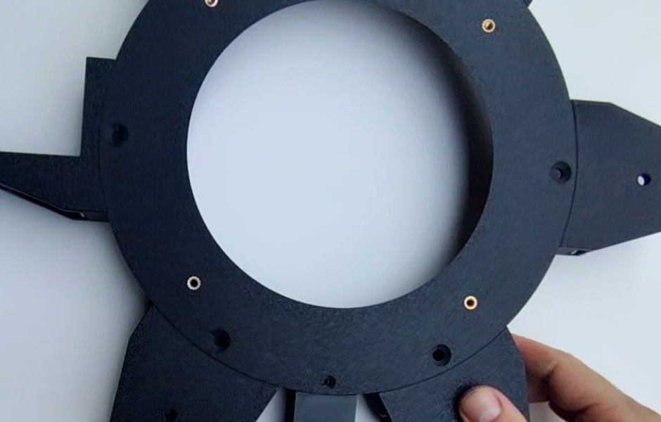
Interface NEMA 23 bracket: 6 × M5 (4 at the corners of the motor plate, 2 in a pair on the centre line) and 1 × M3 (on the tail)
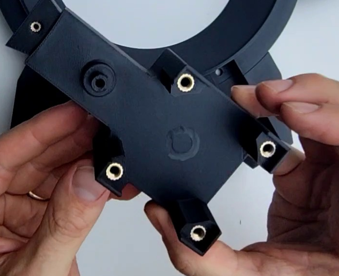
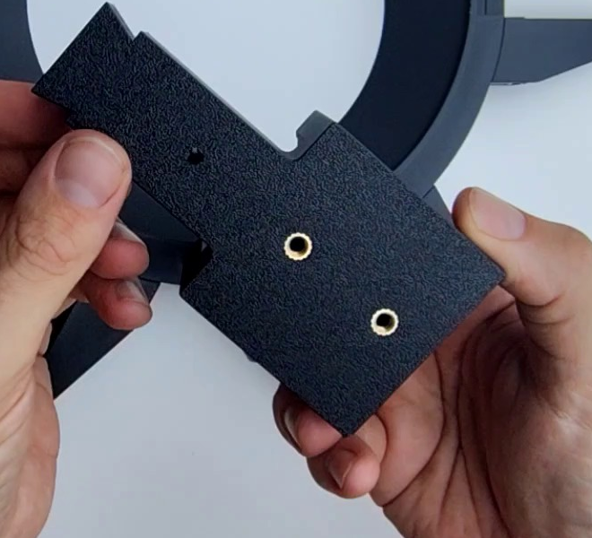
Top interface chute mount: 4 × M4 and 7 × M3
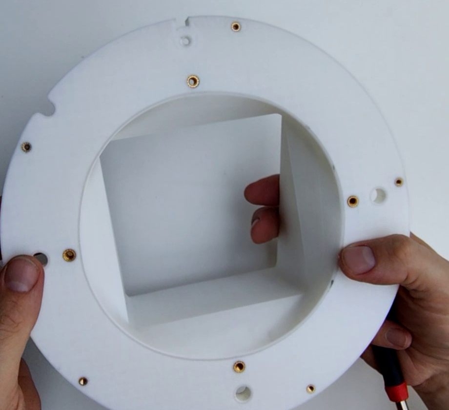
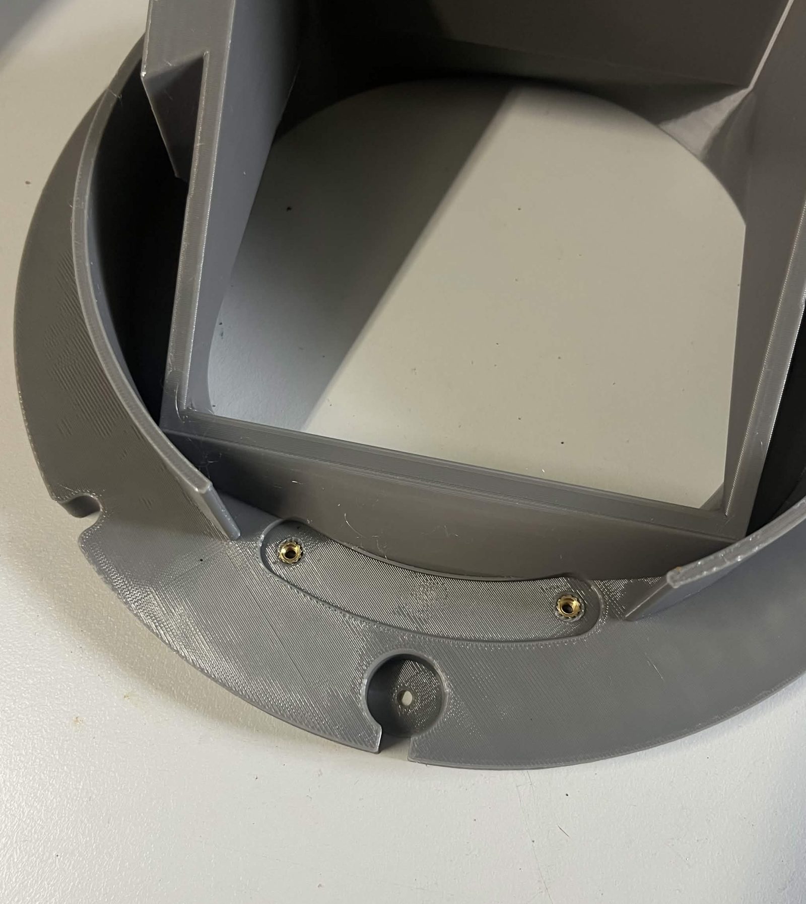
Interface bracket: 3 × M5 (each of the 6)
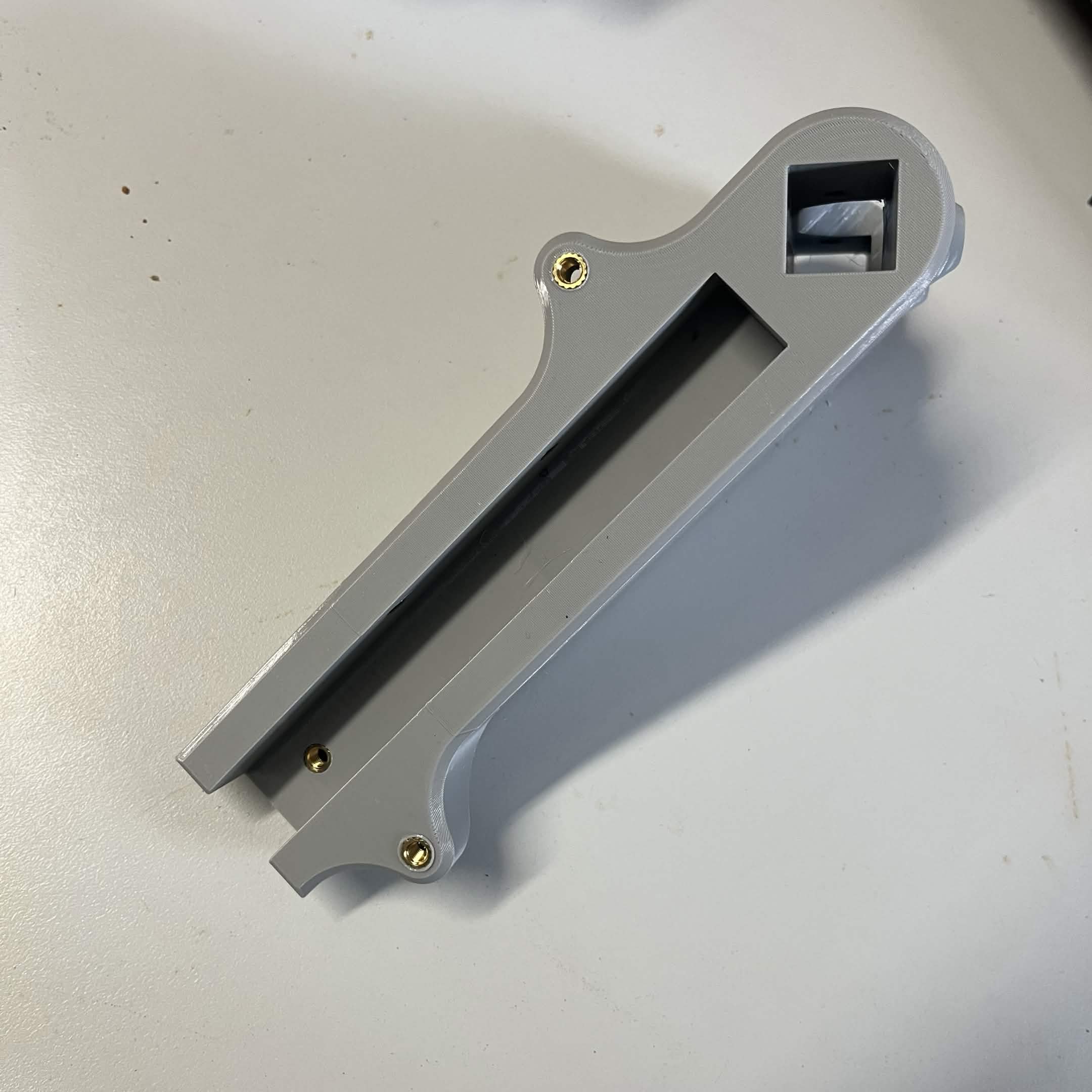
Limit switch housing: 2 × M3
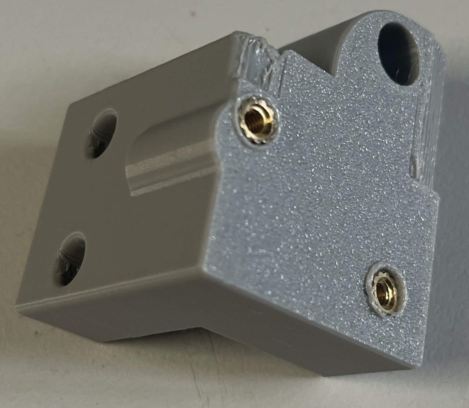
Limit switch hammer: 1 × M3
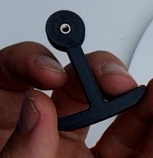
Cable cage bracket (cable mount): 1 × M3

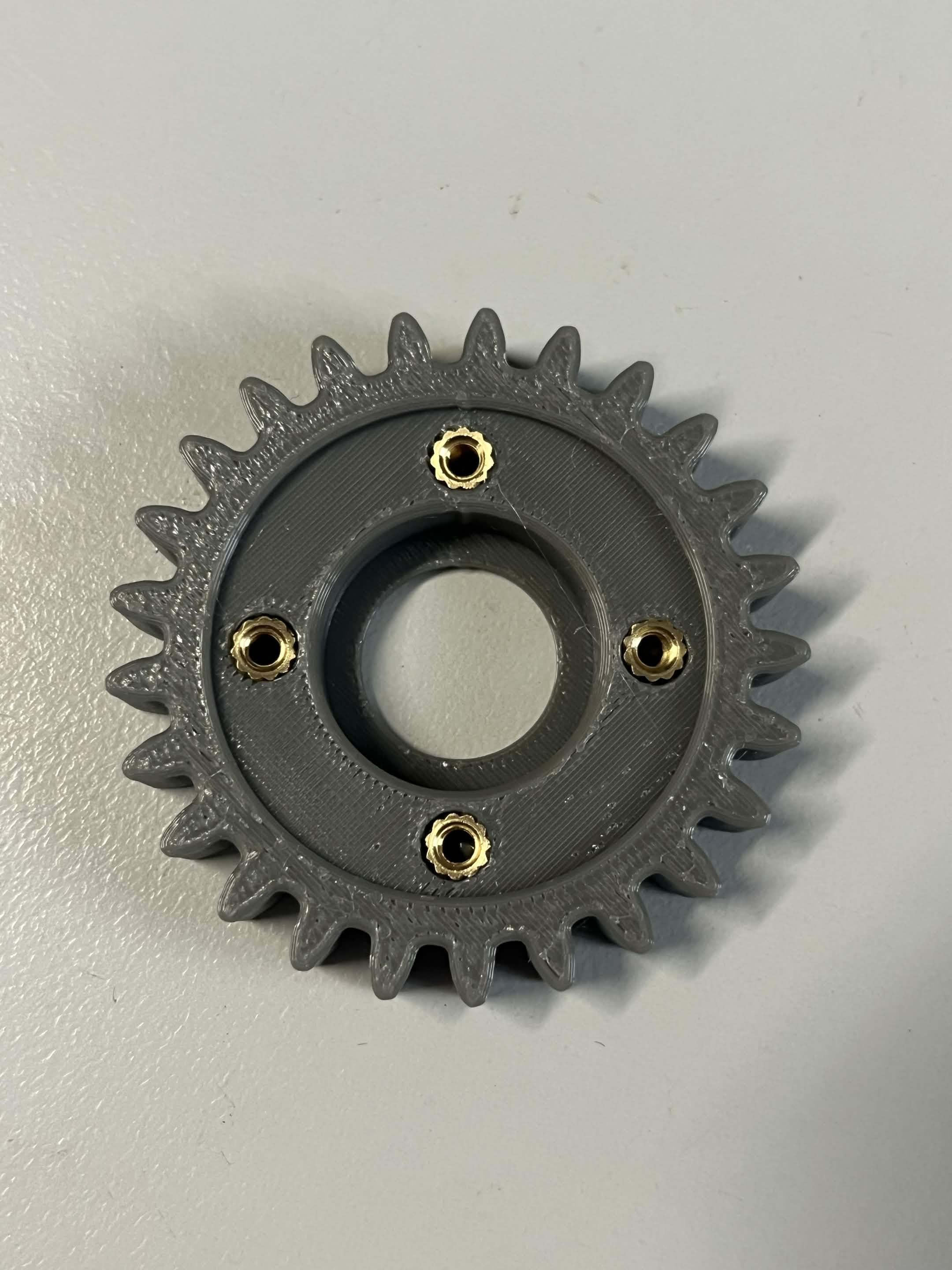
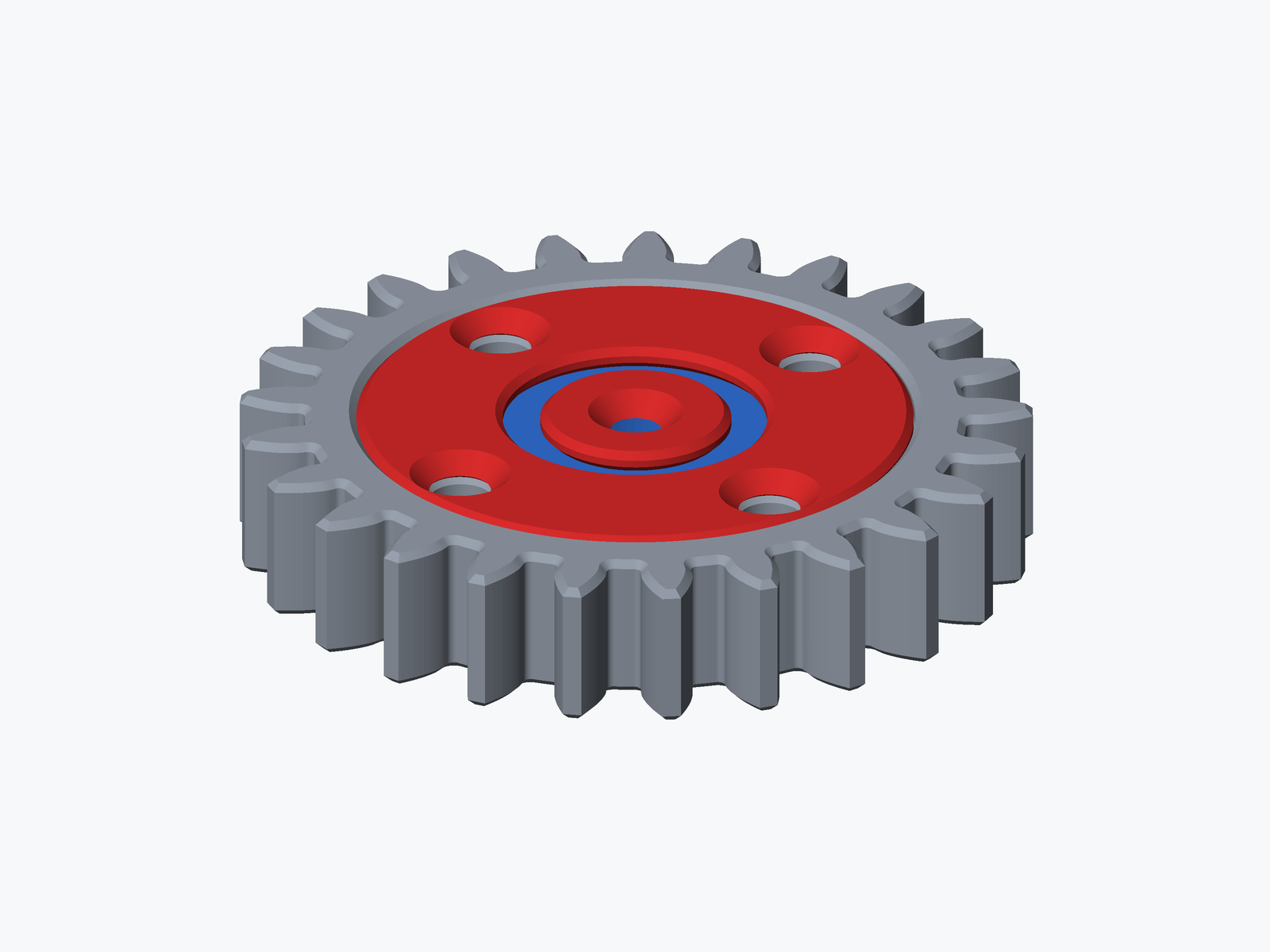
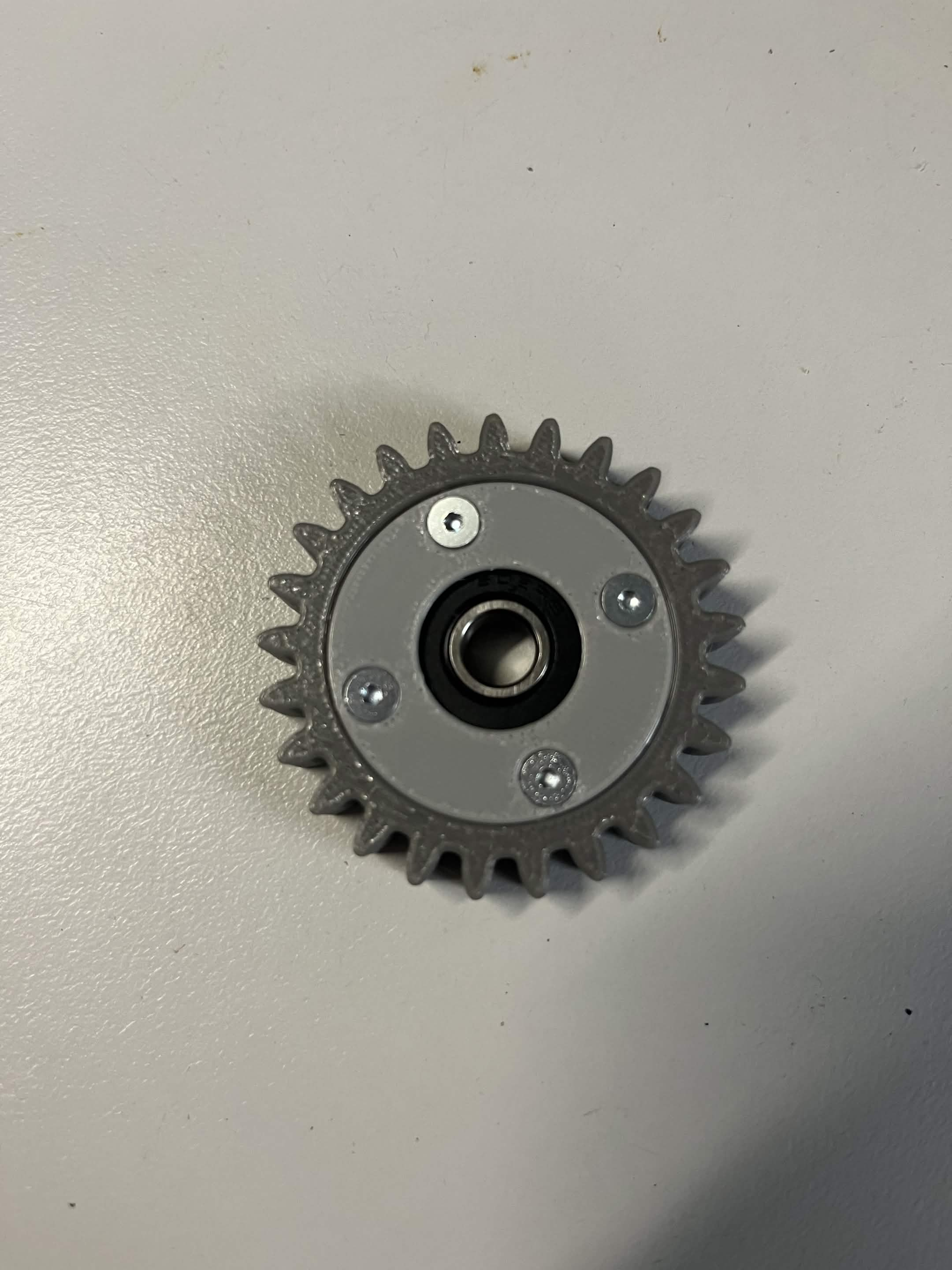
Interface idler gear: 4 × M3, around the bearing pocket on the underside
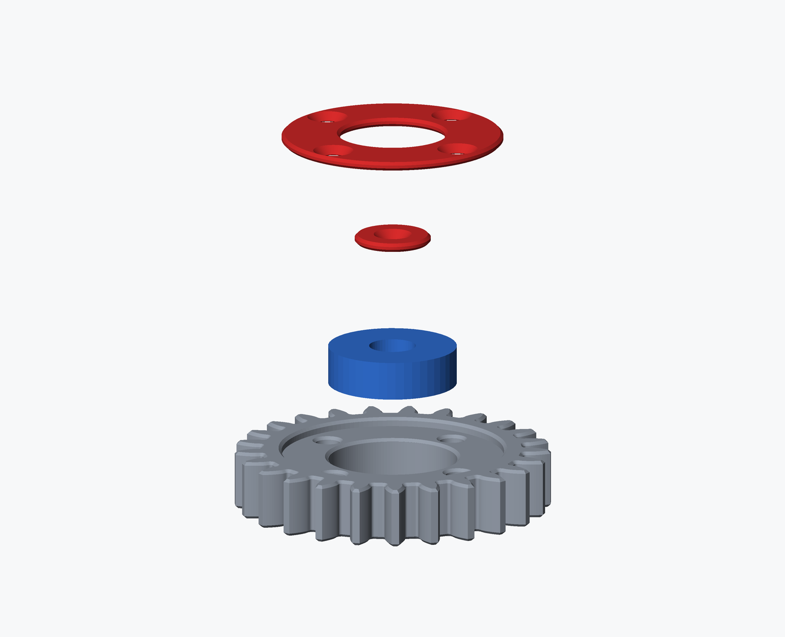
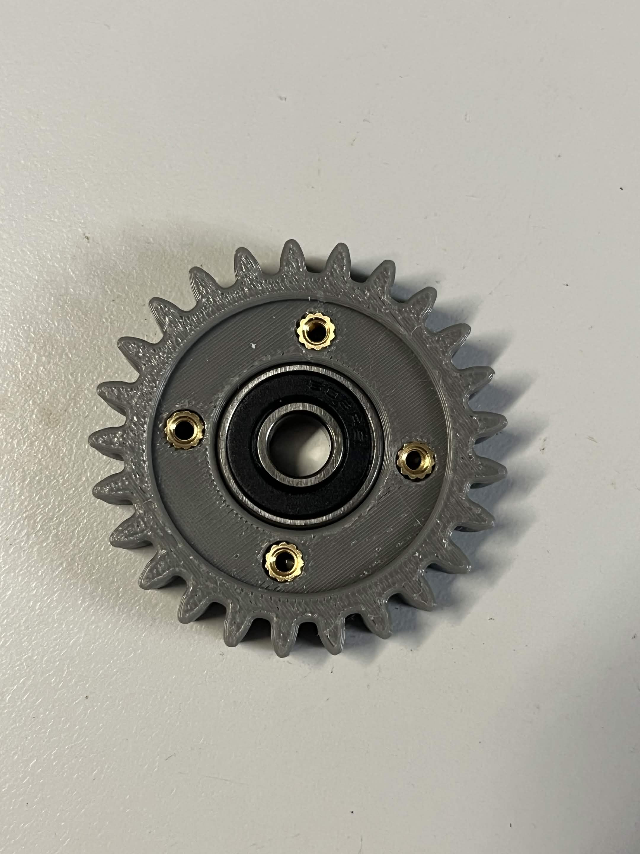
Build the bearing sub-assembly now too, while the gear is still loose — it is easier off the bracket than on it. Push a 608 2RS bearing into the pocket, fit the Chute stepper idler bearing retainer (inner) over the bearing's bore, then the Chute stepper idler bearing retainer (outer) over that, seated flush in the recess with its 4 holes lined up on the gear's 4 inserts. Secure it with 4 × M3 × 8 mm countersunk screws, the same M3 x 8 mm countersunk screw used on the Interface spur gear in step 9. See step 9 for how the idler gear then goes onto the bracket.
Step 2 Attach the interface ribs to the upper fixed section
Heat inserts first: press the 4 × M4 inserts into the Interface upper fixed section and the 6 × M5 and 1 × M3 inserts into the Interface NEMA 23 bracket before you assemble anything here.
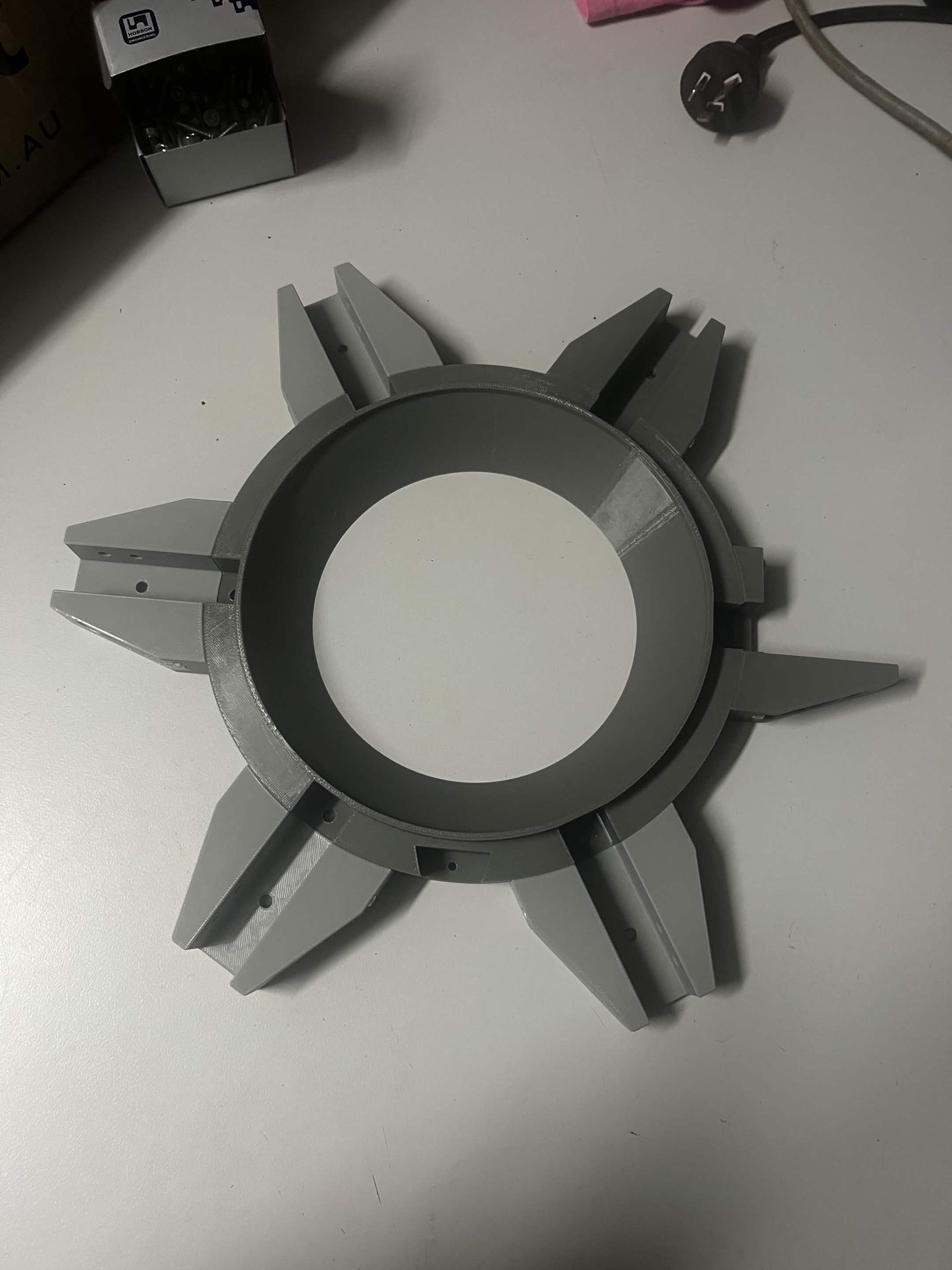
Attach the Interface rib (switch gap) to the Interface upper fixed section, two positions counterclockwise of the stepper-mount notch when viewed from above (see photo). Use two M5 × 16 mm socket / button head screws, tapping directly into the plastic.
Attach the remaining 5 Interface ribs to the Interface upper fixed section, two M5 × 16 mm socket / button head screws each, again tapping into the plastic.
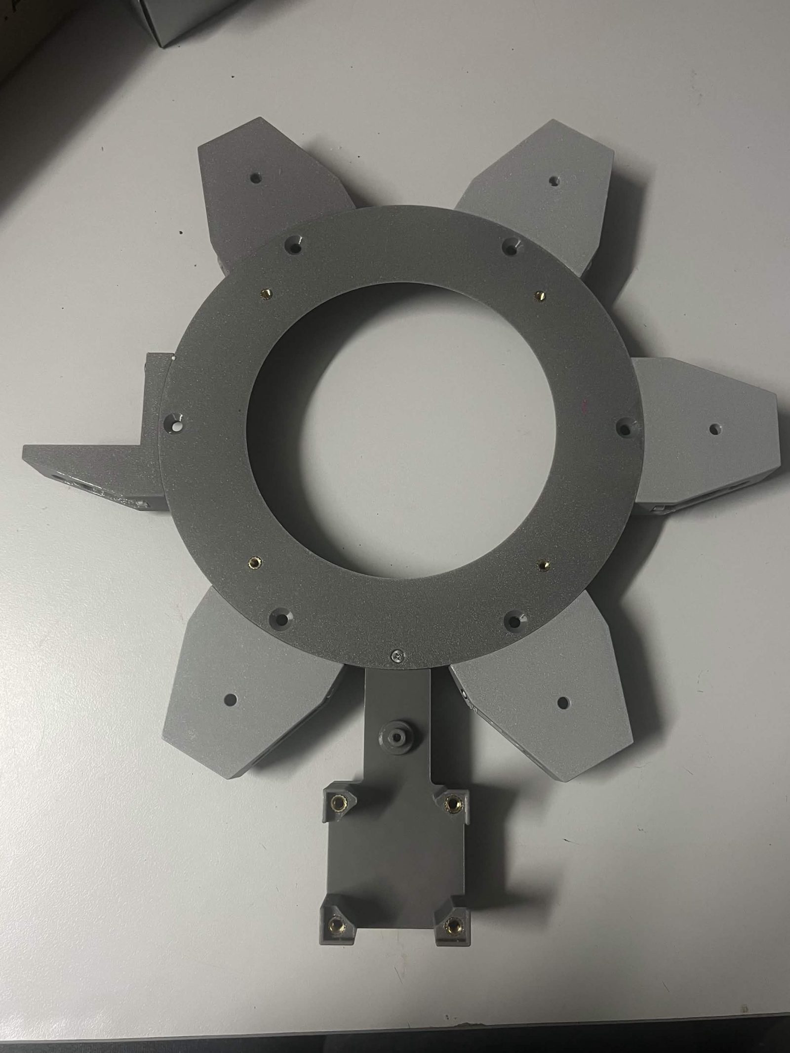
Slot the Interface NEMA 23 bracket into the Interface upper fixed section and secure it from below with an M3 × 12 mm countersunk screw.
Attach the whole assembly to the bottom of the Top plate with 2 M5 × 22 mm countersunk screws, one through hole S2 and one through hole S3, into the Interface NEMA 23 bracket's pair of M5 inserts. Hole S1 stays empty.
Alternative: whether these need a countersunk head depends on how your Top plate was cut. If the S2/S3 holes have a countersink cut in, use a countersunk head; if they don't, M5 × 20 mm socket / button head screws work here instead. Builder's call depending on their plate, the same as the I1-I6/O1-O6 screws in step 5.
Step 3 Prepare the interface brackets
Heat inserts first: each Interface bracket takes 3 × M5 inserts. Press them in before fitting the extrusion.
These six brackets are what the vertical extrusion legs (piece F, step 13) will anchor into once the framing goes on.
Align an Interface bracket with a length of aluminum extrusion, piece E (Interface spoke, long), 238 mm.
Place T-nuts in the extrusion, lined up with the 4 holes on the side of the Interface bracket. See Fitting T-nuts for how they go in.
Slide the extrusion into the Interface bracket, careful not to dislodge the T-nuts, and drive four M5 × 16 mm socket / button head screws into them.
Thread the four screws a couple of turns into the T-nuts before sliding the extrusion in, so they hang in place instead of sitting loose in the channel. Easier than aligning four free T-nuts by feel. Tip: BrickCycleAlice.
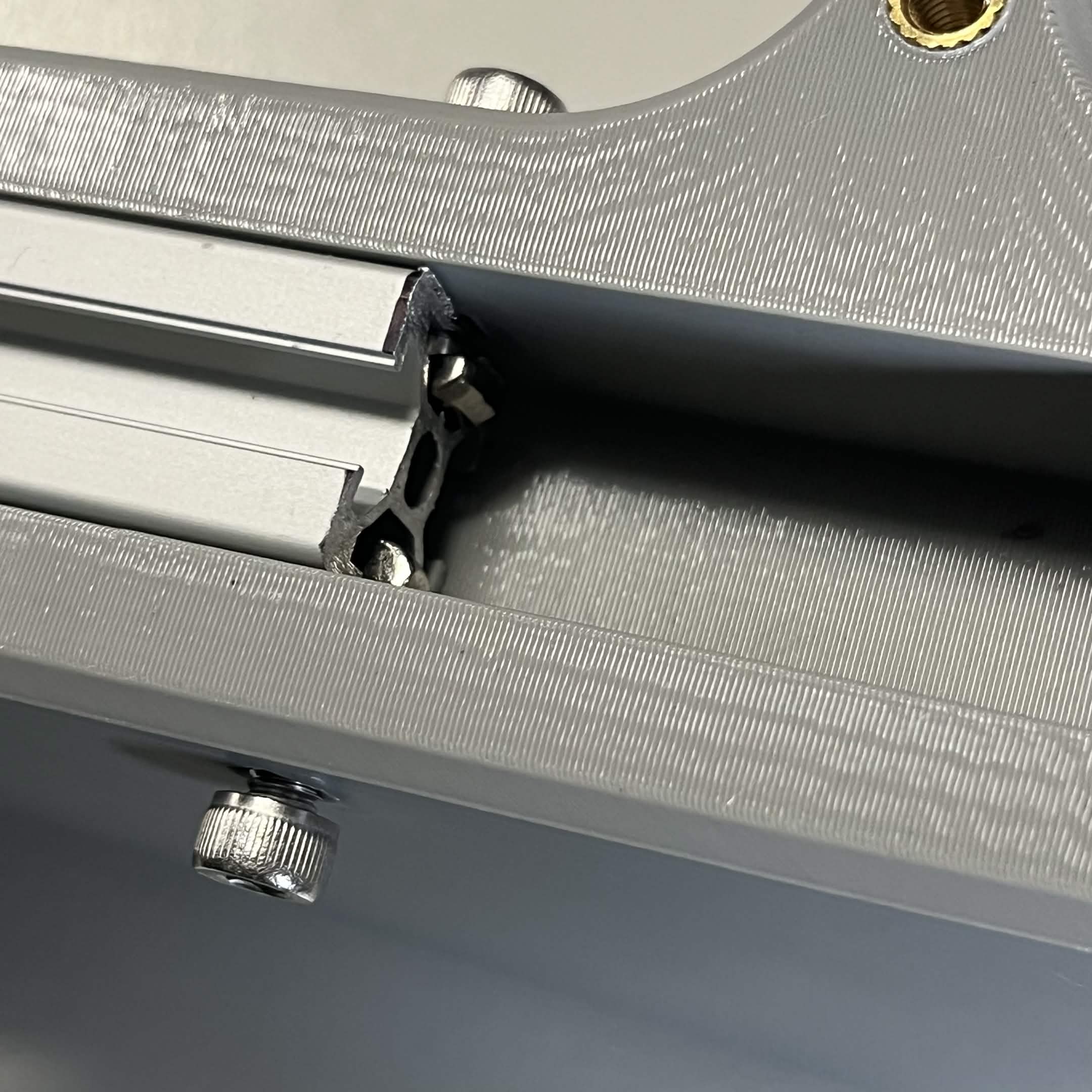
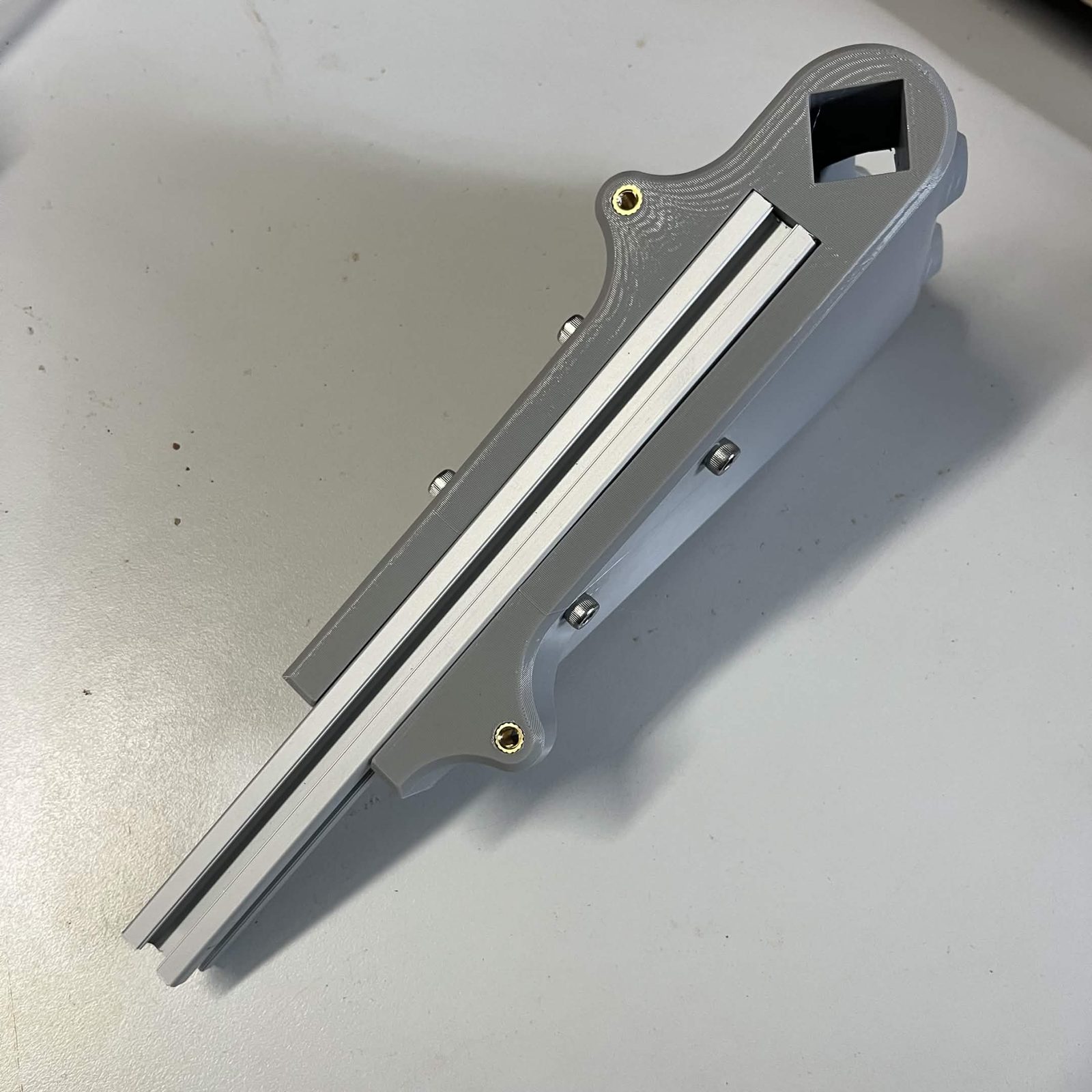
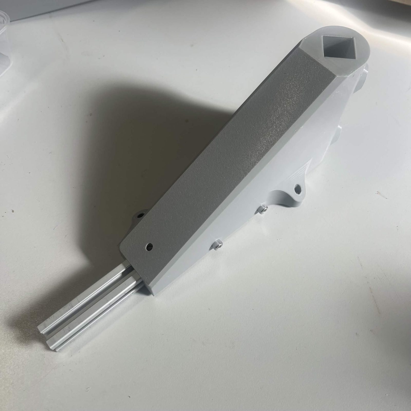
Repeat for all 6 Interface brackets.
Step 4 Prepare the limit switch interface bracket
Heat inserts first: the Limit switch housing takes 2 × M3 inserts. Press them in before assembling it.
This switch is the chute's home reference: because the stepper motor that will drive the chute (step 9) has no inherent sense of position, the machine homes against this switch and hammer on startup to know which bin the chute is aimed at.
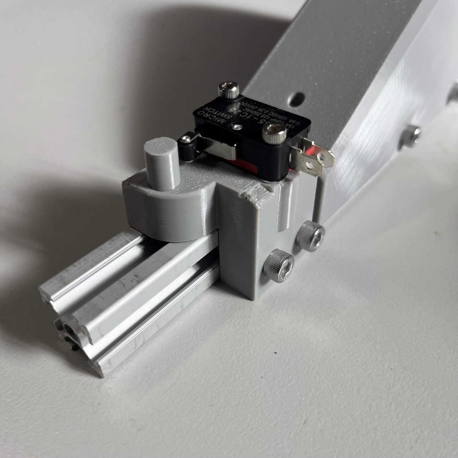
Push the Printed dowel pin into the Limit switch housing.
Attach the Roller lever limit switch (the "endstop-mechanical" part in your kit) with two M3 × 16 mm socket / button head screws (into the housing's 2 M3 inserts) so the roller sits next to the dowel pin.
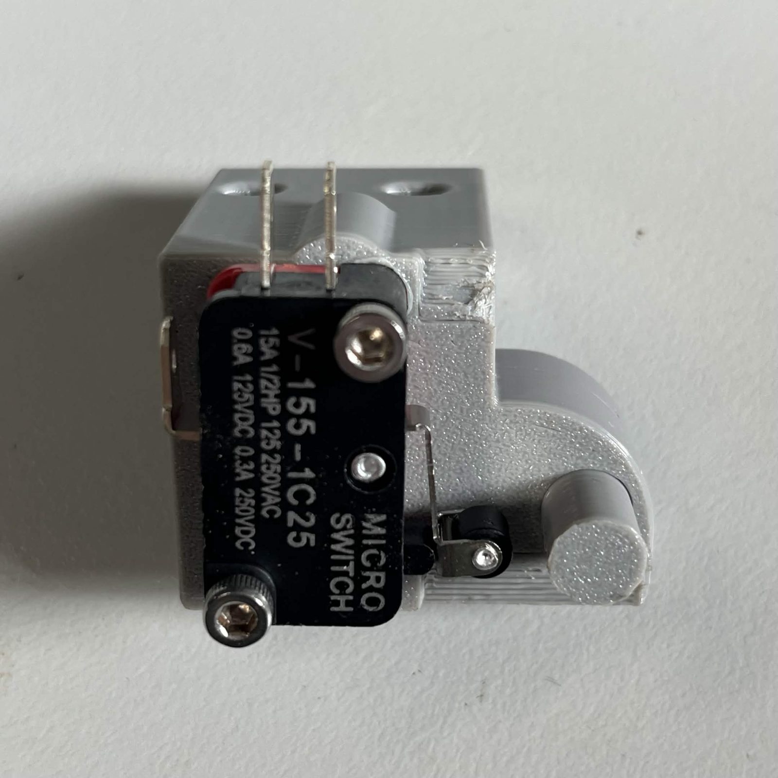
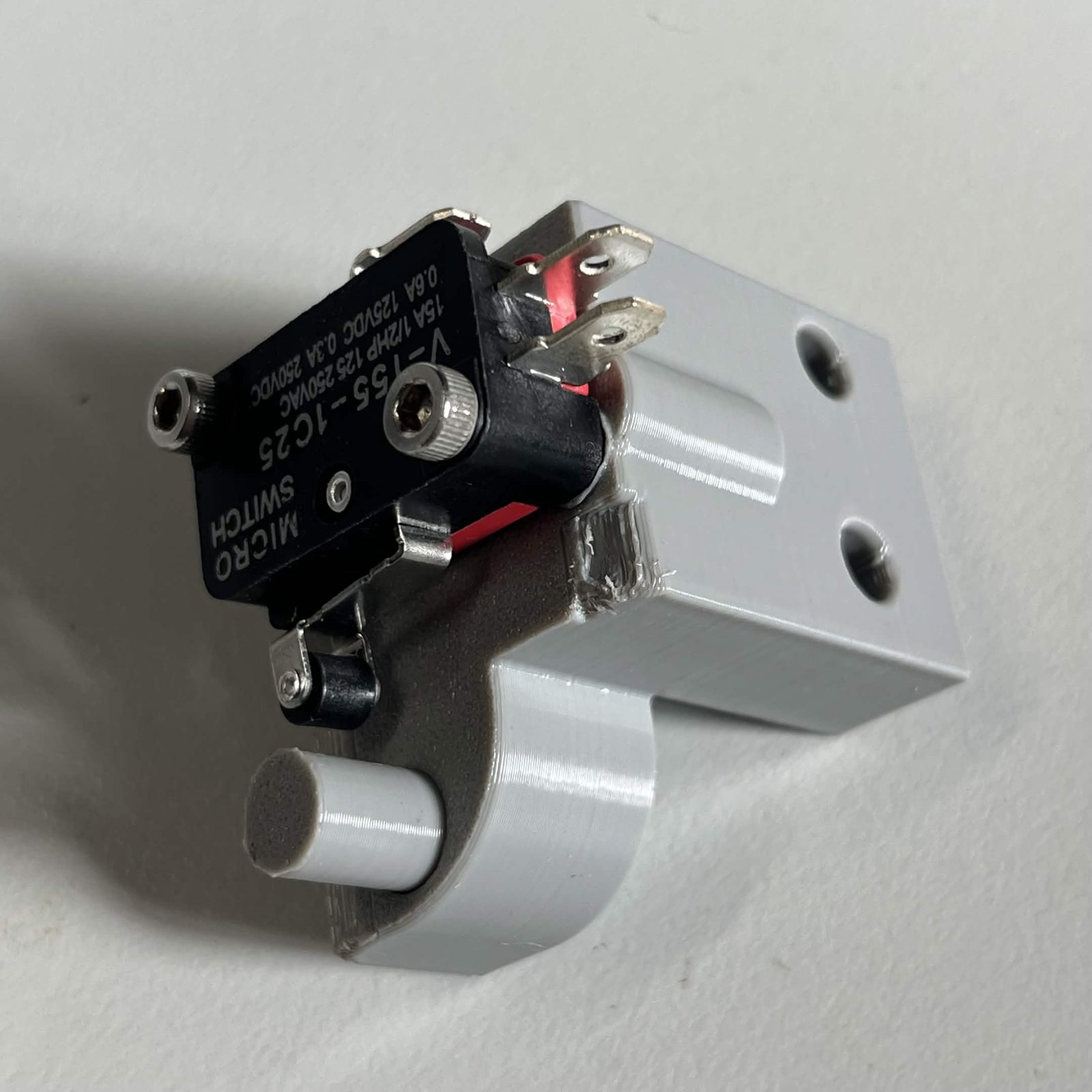
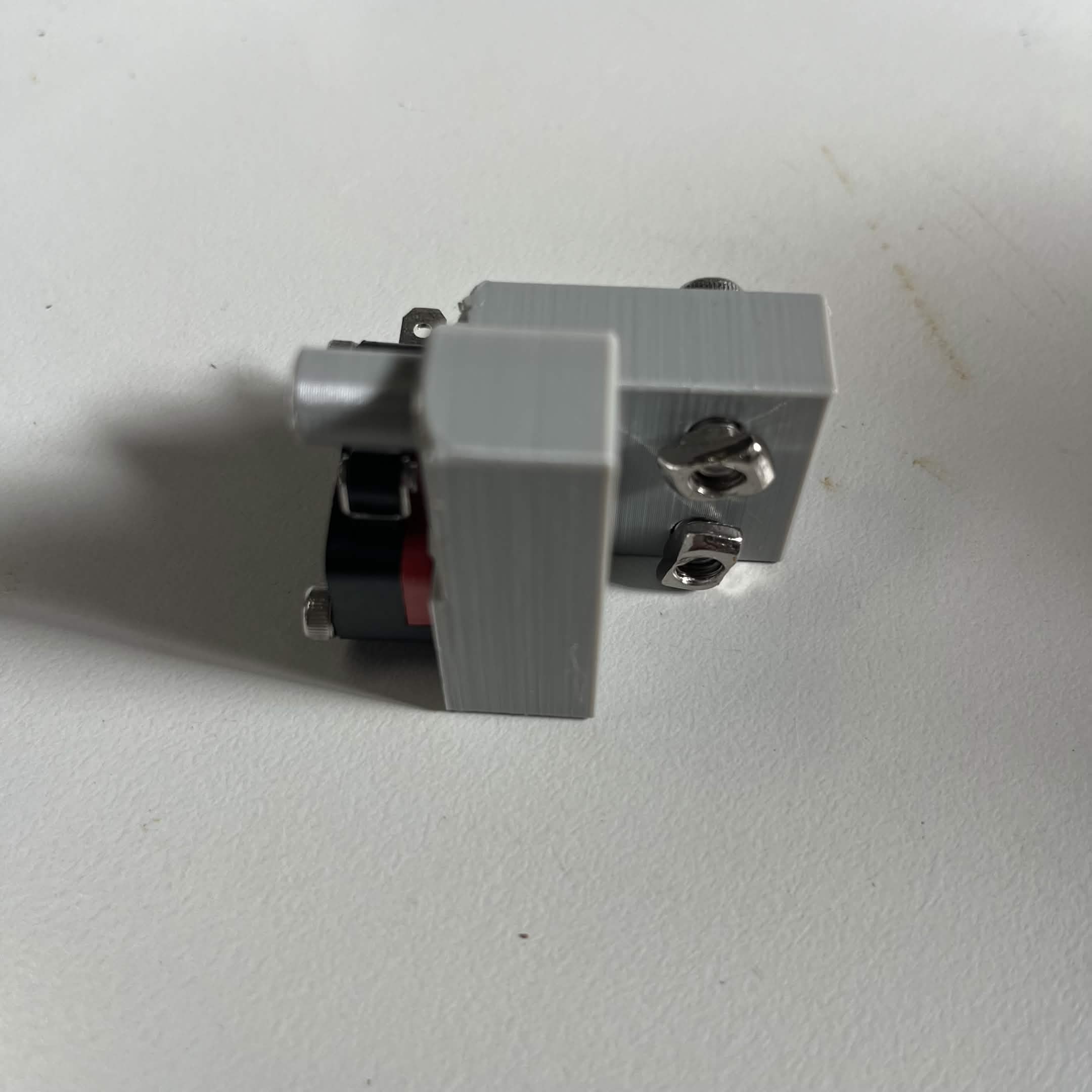
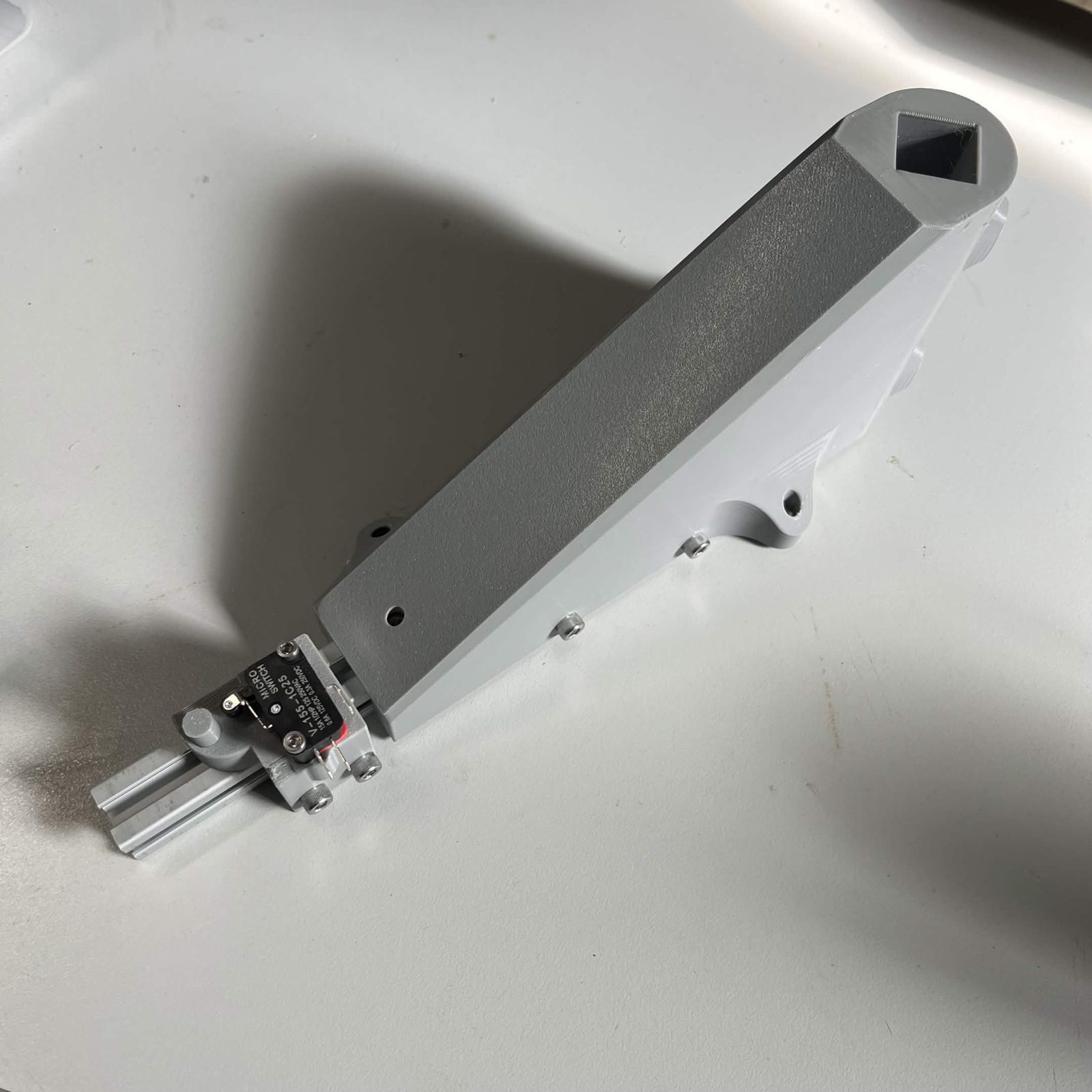
Align the switch housing with the extrusion of one of the prepared Interface brackets so the limit switch is on the same face as the sloped side of the bracket. Slide 2 T-nuts into the extrusion and fasten the Limit switch housing to the extrusion with two M5 × 16 mm socket / button head screws. Slide it as far toward the Interface bracket as possible for now; it gets aligned properly later.
Same trick as the Interface brackets above: thread the two screws into the T-nuts first, then slide the extrusion in with them already hanging in place. Tip: BrickCycleAlice.
Step 5 Install the brackets
Slide a T-nut just into the end of the extrusion of the limit switch interface bracket. Slide the extrusion into the Interface rib (switch gap) and Interface upper fixed section, securing it loosely with an M5 × 8 mm countersunk screw. Slide the extrusion slightly in and out to align the holes on the Interface bracket with the holes on the Top plate, then tighten the screw.
Keep this loose for now, the bracket also gets fixed through the Top plate in the next step. Check by looking straight through the Top plate's own screw hole, not by feel alone. Tip: BrickCycleAlice.
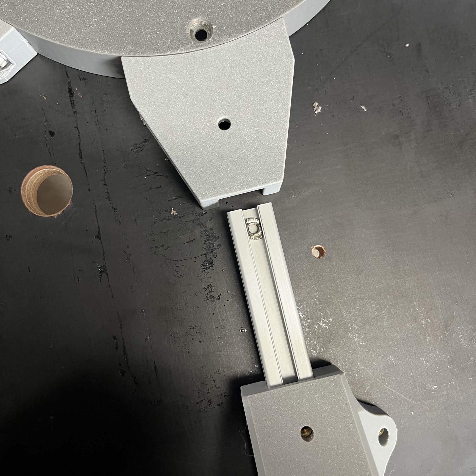
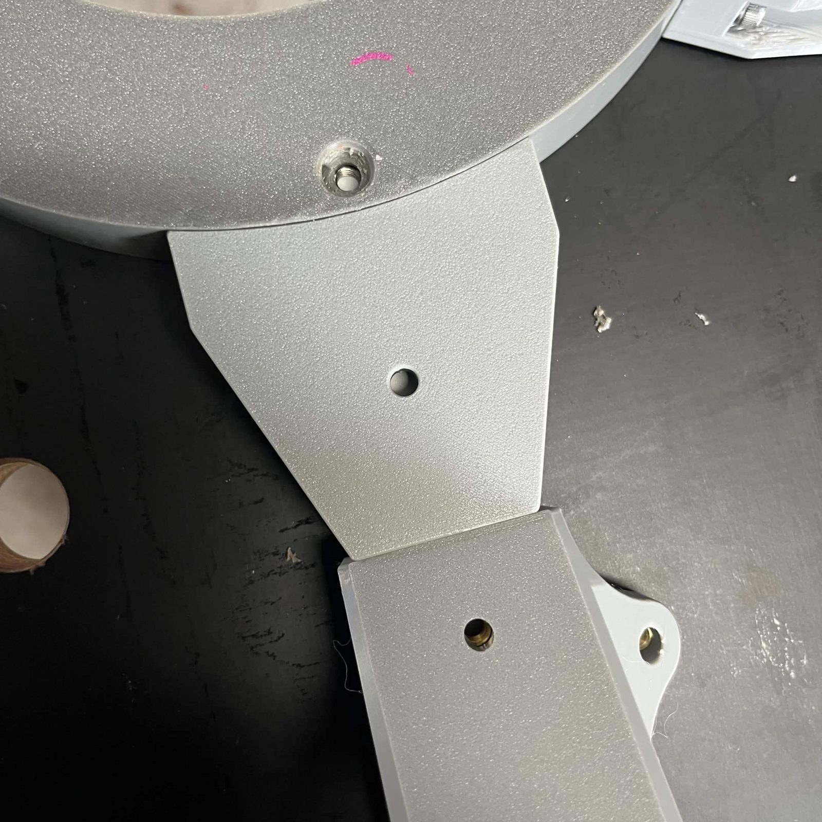
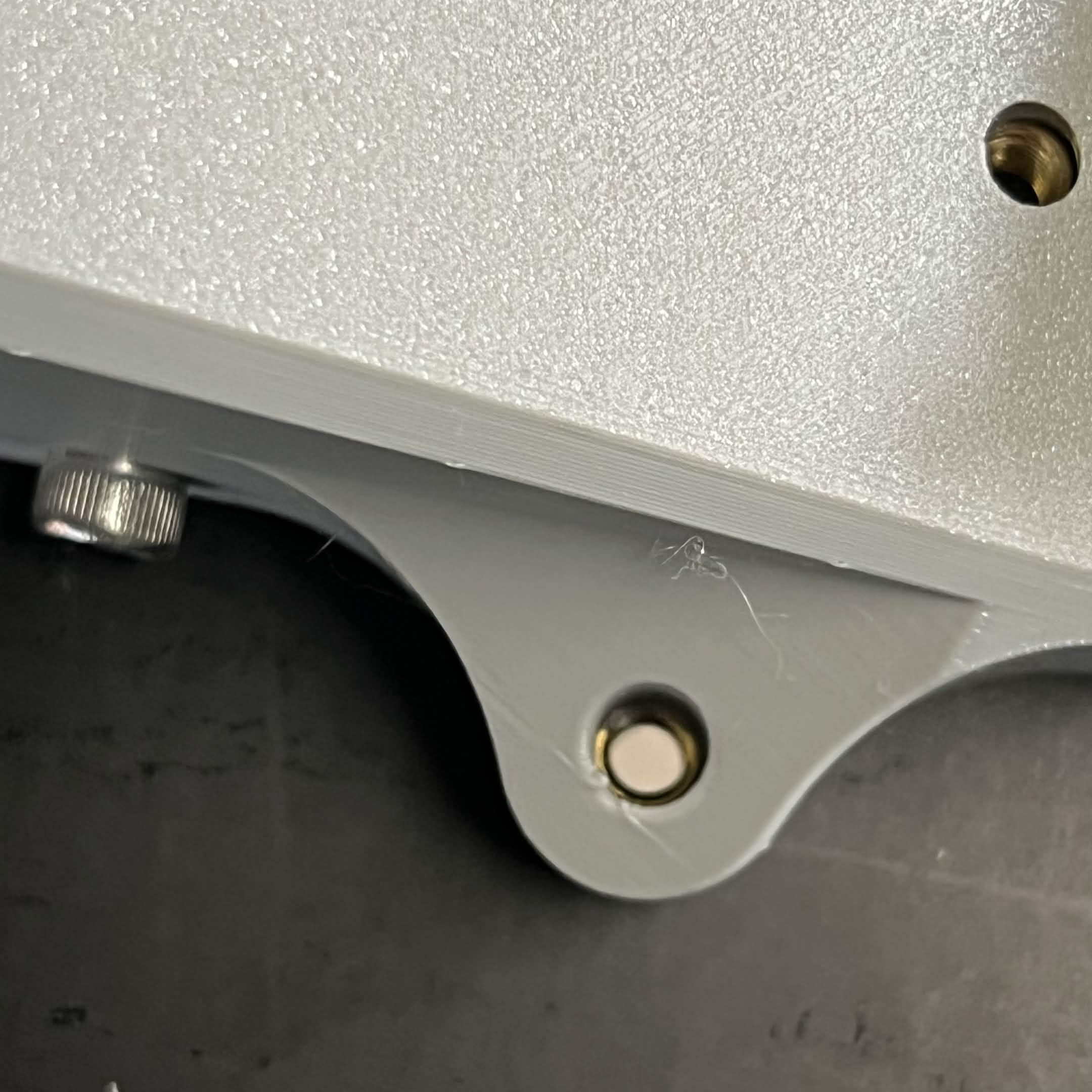
The M5 × 8 mm is a snug fit here, it barely reaches the T-nut. Opening the countersink a little and tightening firmly gets the head to sit flush.
Repeat with the 5 other prepared Interface brackets into the 5 other Interface ribs.
Flip the whole assembly and screw all 6 Interface brackets into place with 12 M5 × 22 mm countersunk screws, one through each of holes I1 to I6 and O1 to O6.
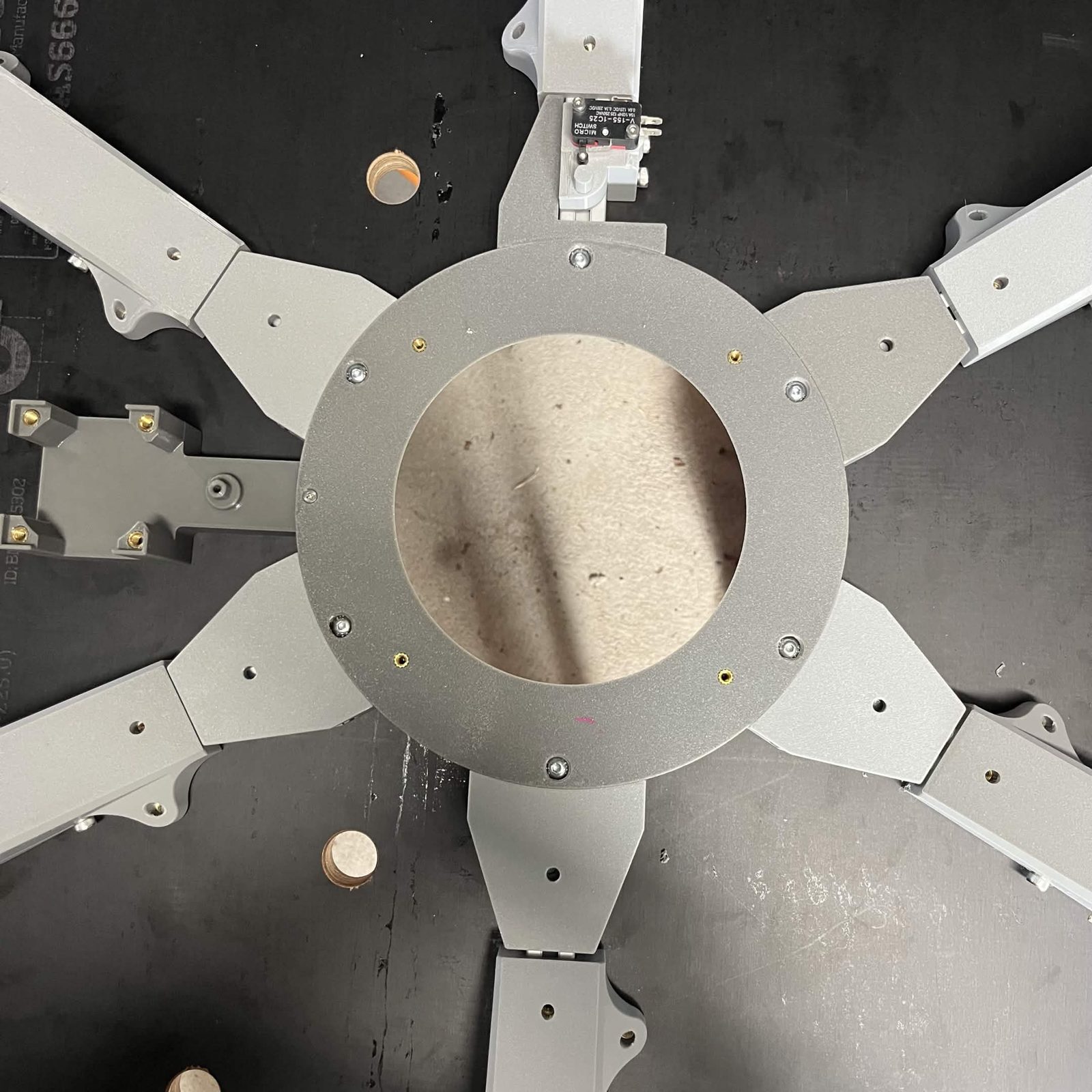
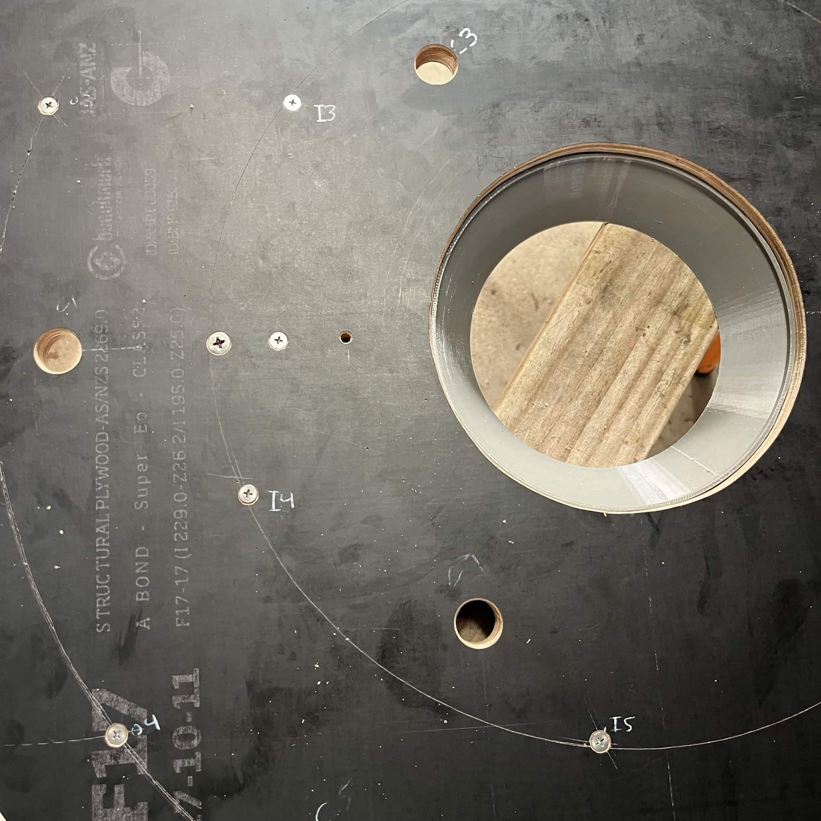
Alternative: the Top plate's laser-cut holes are not countersunk, so a countersunk head does not seat flush. M5 × 20 mm socket / button head screws work here instead.
Go back and fully tighten the M5 × 8 mm screws left loose earlier in this step, now that each bracket is also bolted through its I/O holes. This is also where a hand-cut Top plate's I/O holes show up as inaccurate, if they do; widen them if a bolt is binding. Tip: BrickCycleAlice.
Step 6 Prepare the interface chute gear and mount
Heat inserts first: the Top interface chute mount takes 4 × M4 and 7 × M3 inserts, and the Limit switch hammer takes 1 × M3. Press them in before assembling.
Slot the Limit switch hammer into the Top interface chute mount, then secure it from below with an M3 × 6 mm countersunk screw (into the hammer's M3 insert).
The M3 × 6 mm screw head must sit completely flush with the printed Top interface chute mount. It lies inside the Lazy Susan's rotation path, so a raised head will catch.
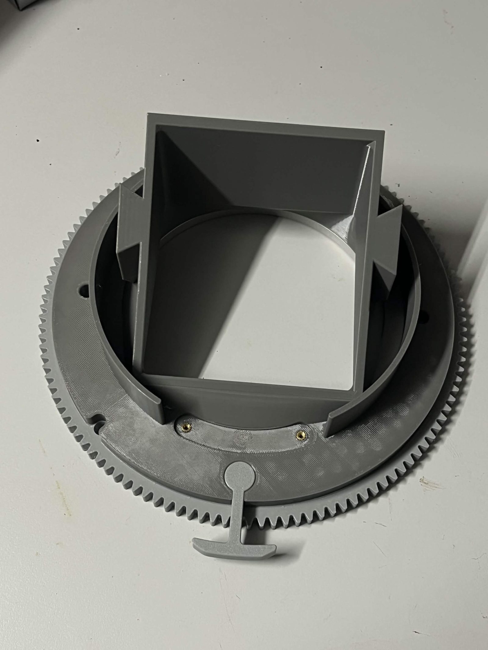
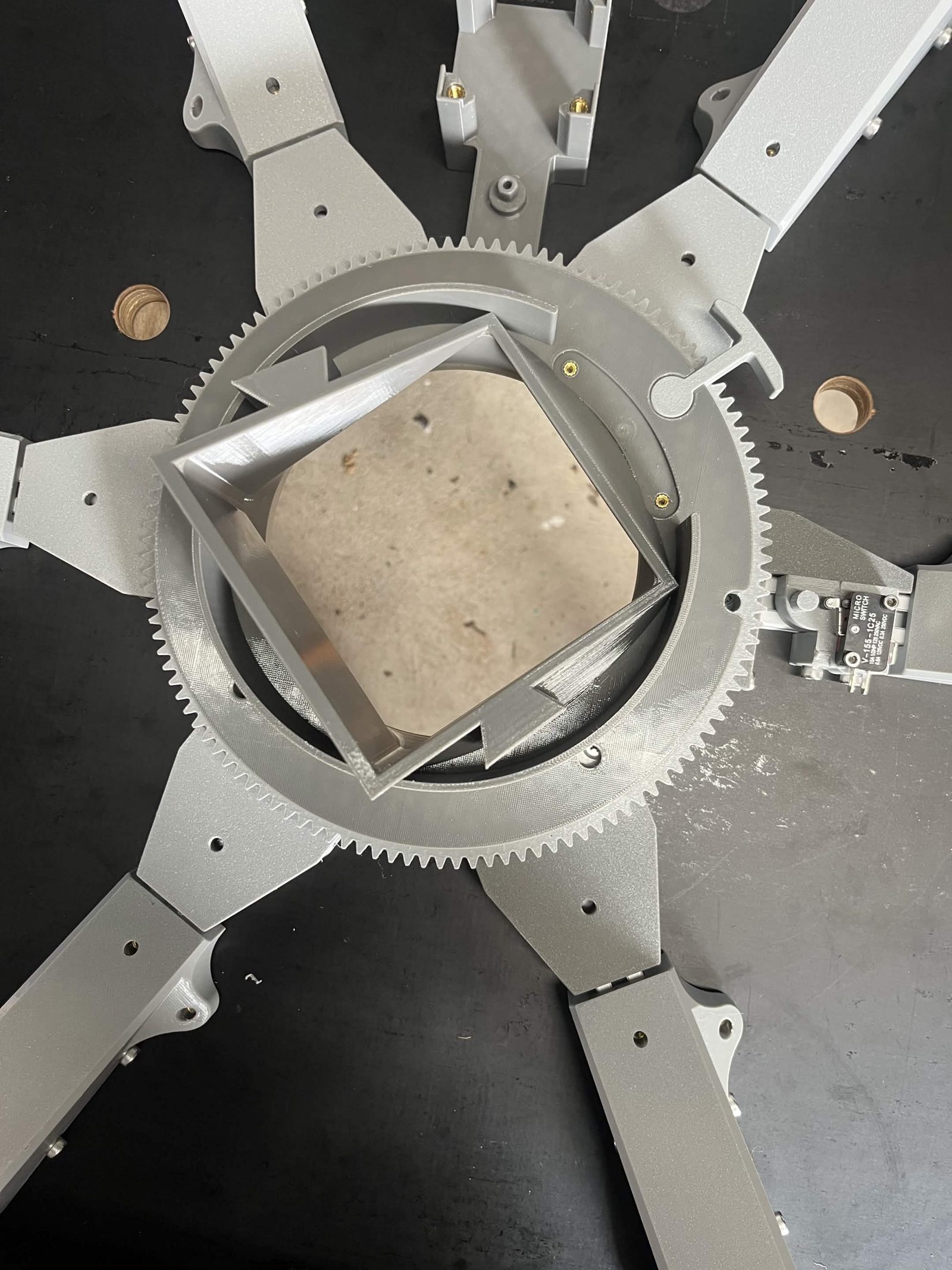
Align the Chute gear on the Top interface chute mount with the notch by the screw for the Limit switch hammer. Attach it with five M3 × 12 mm countersunk screws.
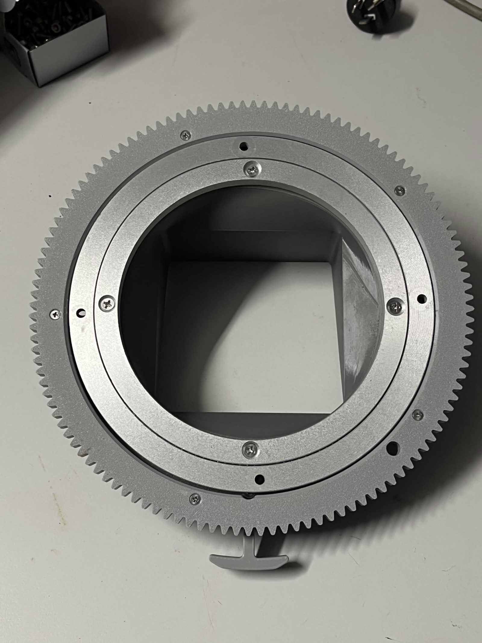
Align the Top interface lazy Susan washer with the 4 inner heat inserts on the Top interface chute mount. Align the inner ring of the Lazy Susan with these 4 heat inserts too. Screw the Lazy Susan into position through the washer and into the Top interface chute mount with four M4 × 16 mm countersunk screws.
These screws have to be very tight. A drill or electric screwdriver will not get them there, so finish them with a hex key by hand. Machine vibration works a loose one out.
Once complete, the free section of the Lazy Susan should rotate freely.
Step 7 Attach the interface chute to the assembly
Place the Interface big spacer on the Interface upper fixed section with its 4 holes lined up with the 4 heat inserts.
Rotate the free part of the Lazy Susan on the chute mount assembly from step 6 so that 3 of its holes line up with the holes in the Top interface chute mount. Place the assembly on top of the Interface big spacer with the 3 holes aligned with 3 of the heat inserts. Screw these together tightly with three M4 × 16 mm countersunk screws.
Rotate the Top interface chute mount 90 degrees relative to the Interface upper fixed section to reveal the 4th screw hole in the Lazy Susan (it should also line up with a hole in the Interface big spacer and a heat insert). Drive a fourth M4 × 16 mm countersunk screw tightly through this hole.
Once done, check that the chute rotates freely relative to the Interface upper fixed section.
Step 8 Adjust the limit switch
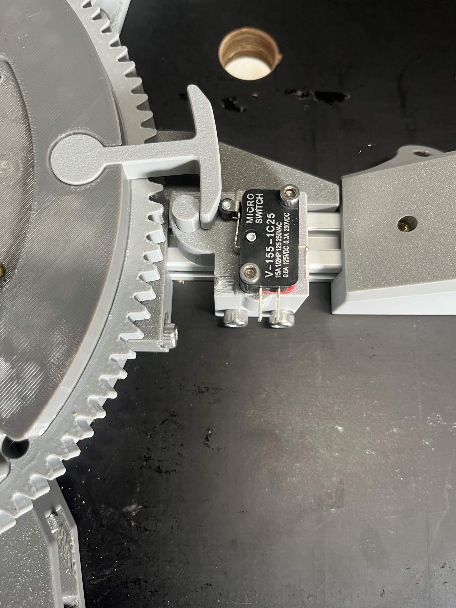
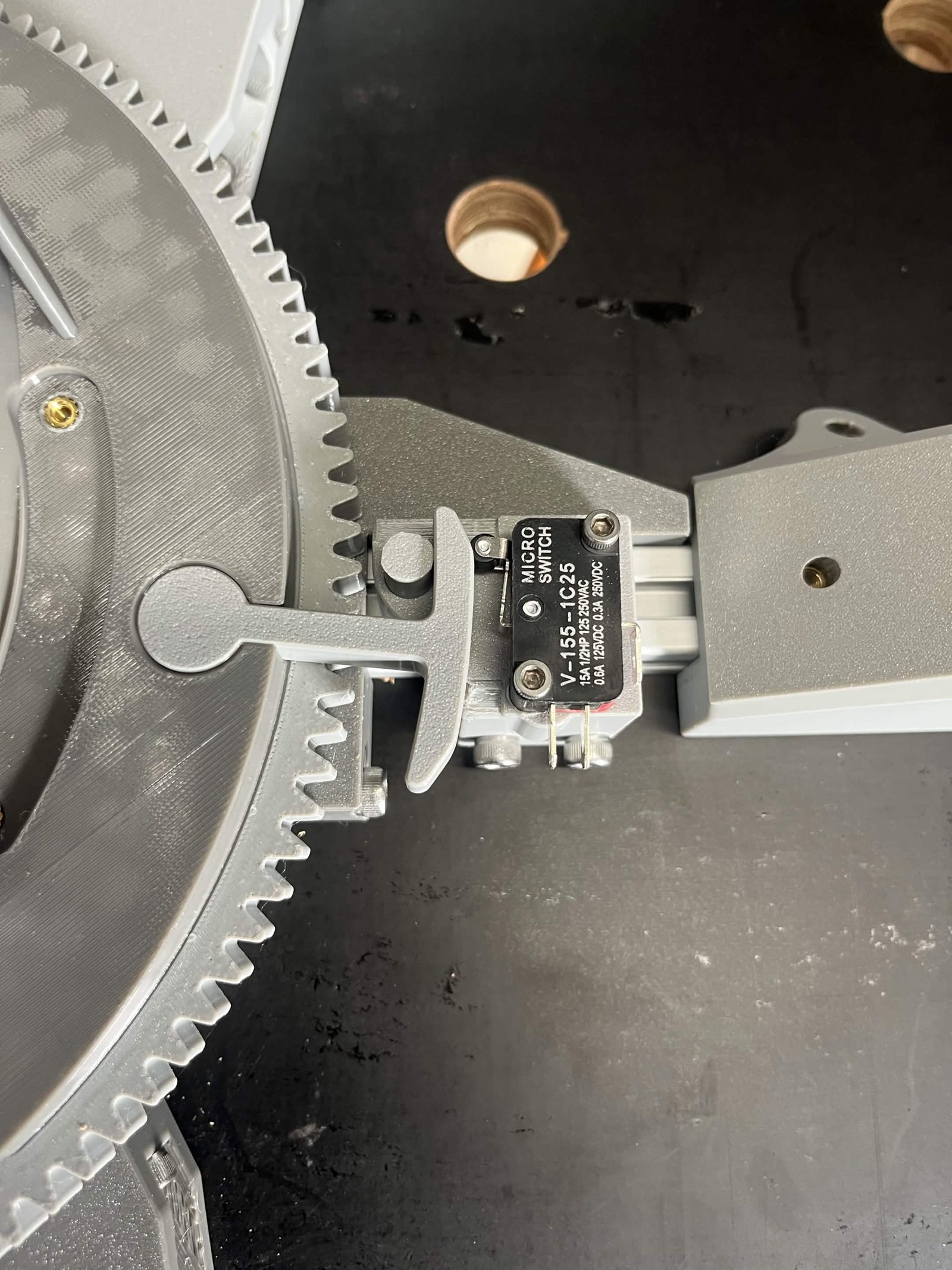
Loosen the screws attaching the Limit switch housing to the extrusion. Slide the housing so the Limit switch hammer passes between the Roller lever limit switch and the Printed dowel pin. The hammer has to strike the switch from both directions of rotation, and it must not run on the dowel pin. Rotate the chute slowly to each limit by hand: you should feel and hear the switch click just before the hammer would otherwise hit the dowel pin. If the hammer rubs against the dowel pin, slide the housing slightly further away and re-test. Tighten the screws to keep the housing in this position.
Step 9 Install the chute stepper motor
This video predates the idler gear's bearing retainer caps. It shows the idler gear built the old way, with a loose washer under the M3 × 35 screw instead of the two printed caps from step 1.
The idler gear bridges the gap between the spur gear on the motor shaft and the chute's ring gear (built in step 6), so the motor can sit off to the side of the chute mount rather than driving it directly.
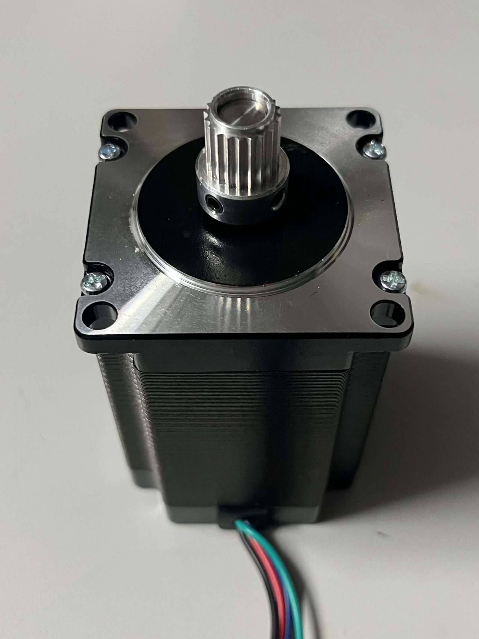
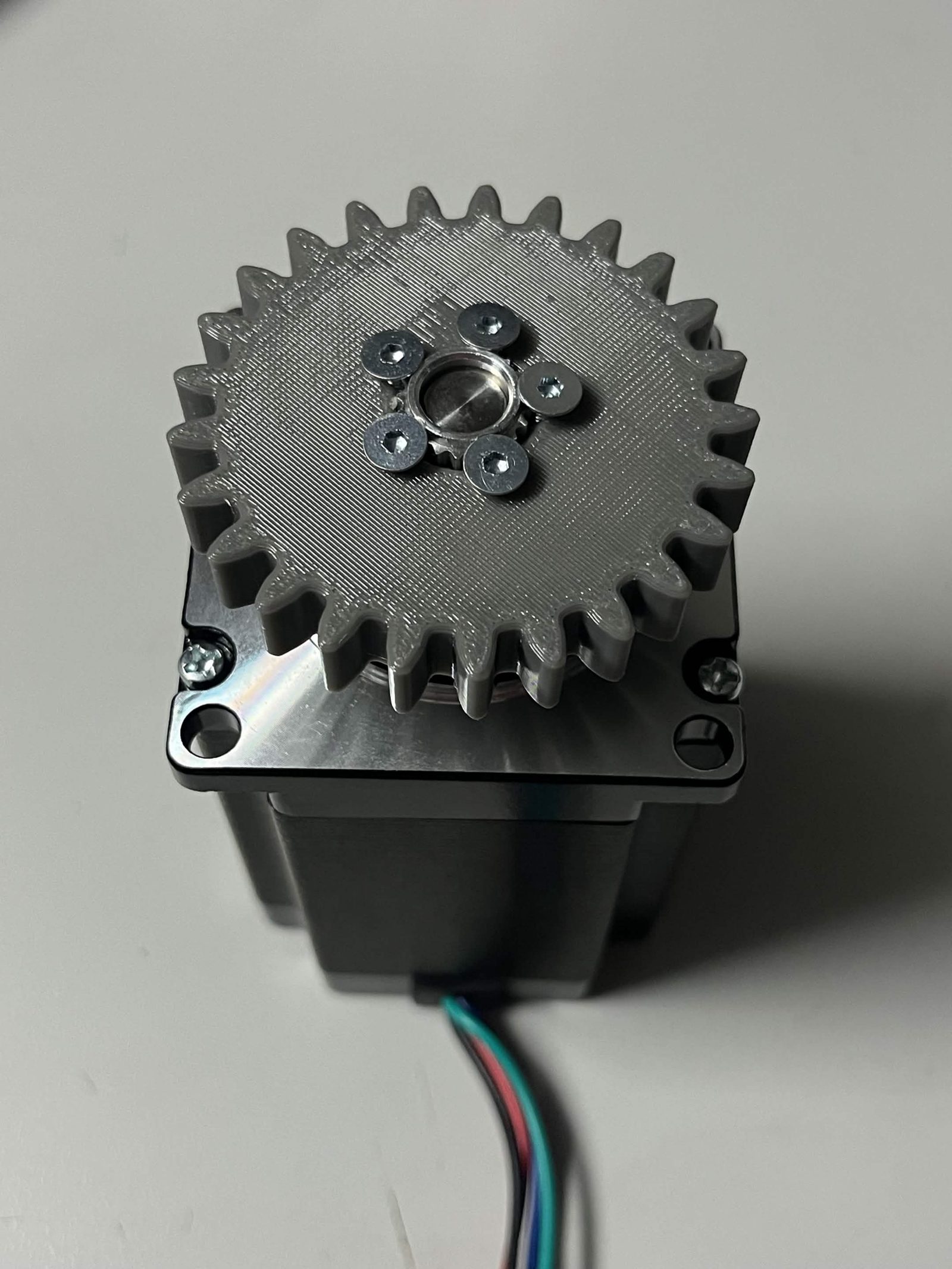
Slide the prepared Timing pulley over the shaft of the NEMA 23 stepper motor and tighten its two set screws (grub screws). Slide the Interface spur gear onto the Timing pulley and secure it with five M3 × 8 mm countersunk screws: three tapped into the Interface spur gear and two bracing against the Timing pulley (exact split may vary — check the hole pattern in the photo).
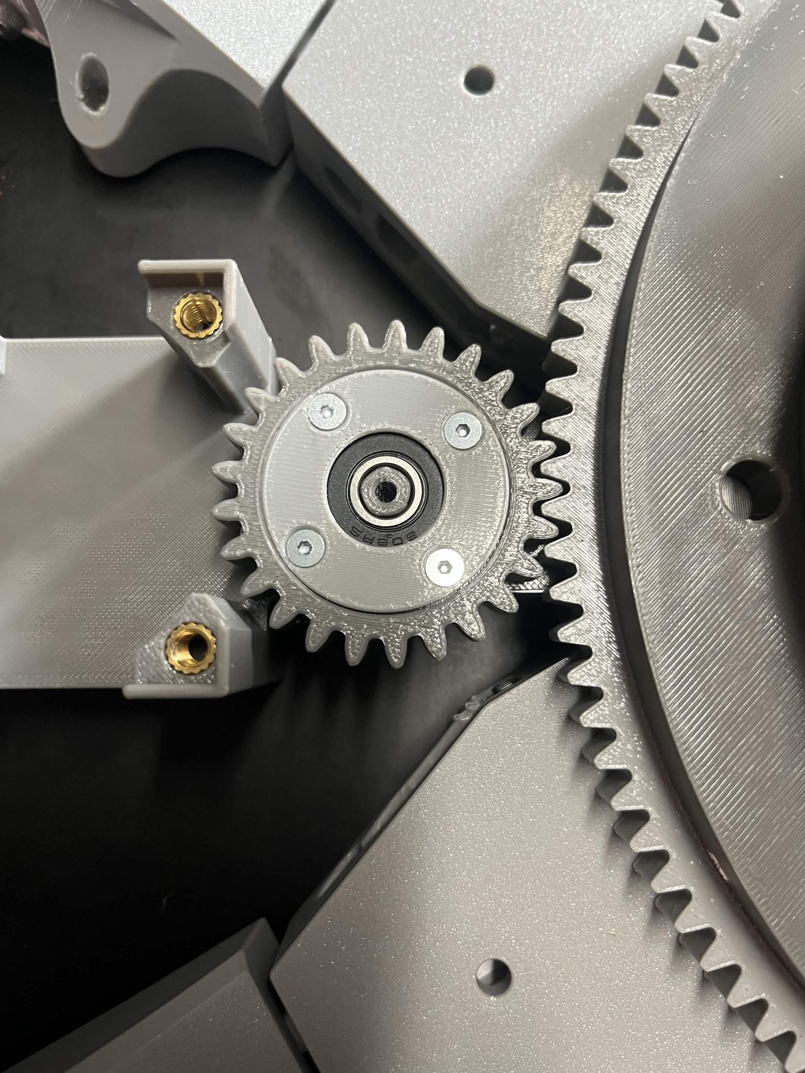
Push the prepared Interface idler gear — bearing, inner retainer cap, and outer retainer already fitted, see step 1 — onto the Interface NEMA 23 bracket with the bearing facing outwards.
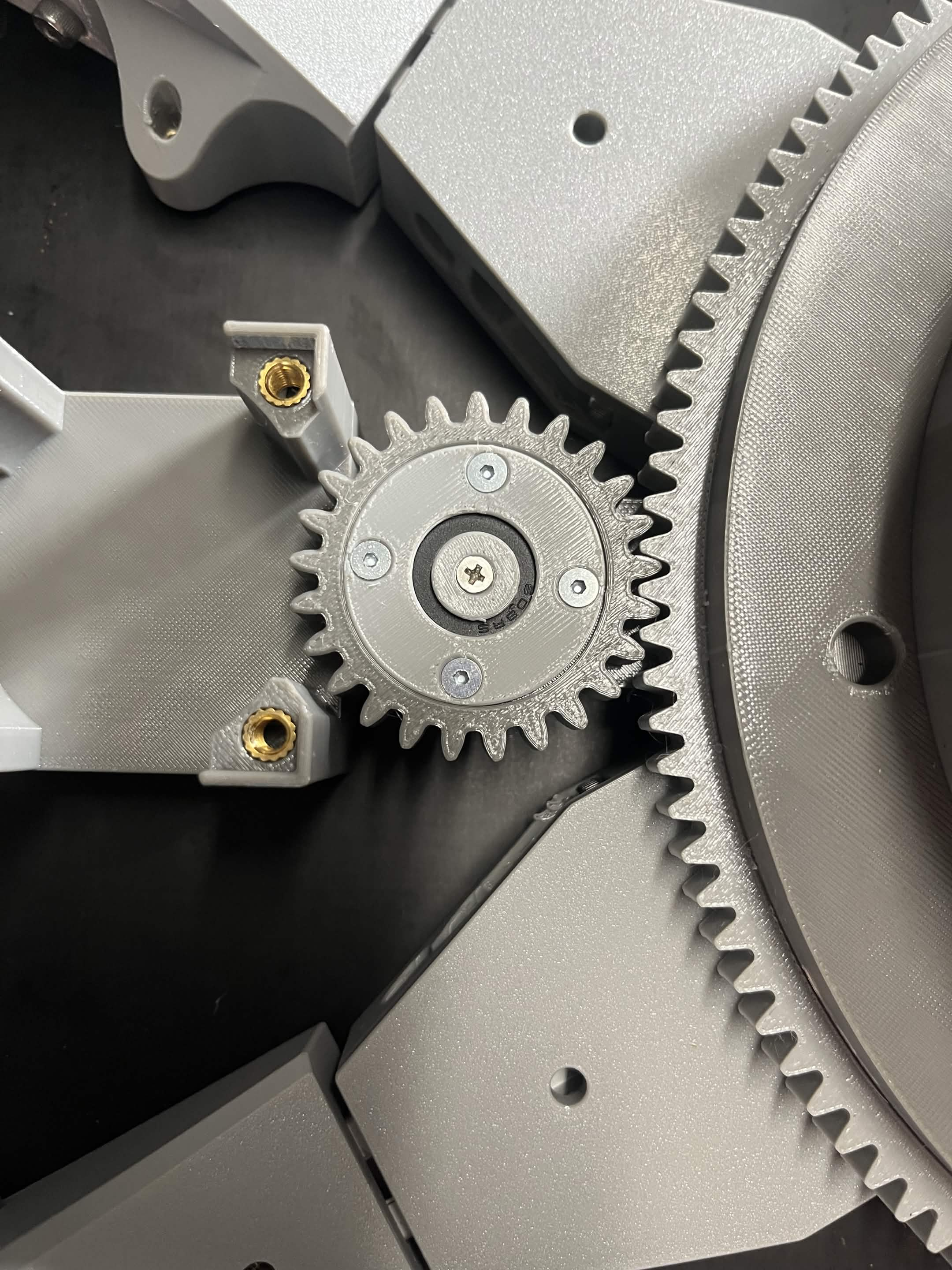
Drive an M3 × 20 mm countersunk screw through the middle of the gear and into the bracket, so its head lands on the inner retainer cap. Tighten until it's seated, then check that the idler gear still spins freely.
Use a countersunk (flat/pancake) head here, not a socket or button head. If you only have a pan head on hand, hand-rotate the chute past this screw and check it clears the Limit switch hammer before closing everything up.
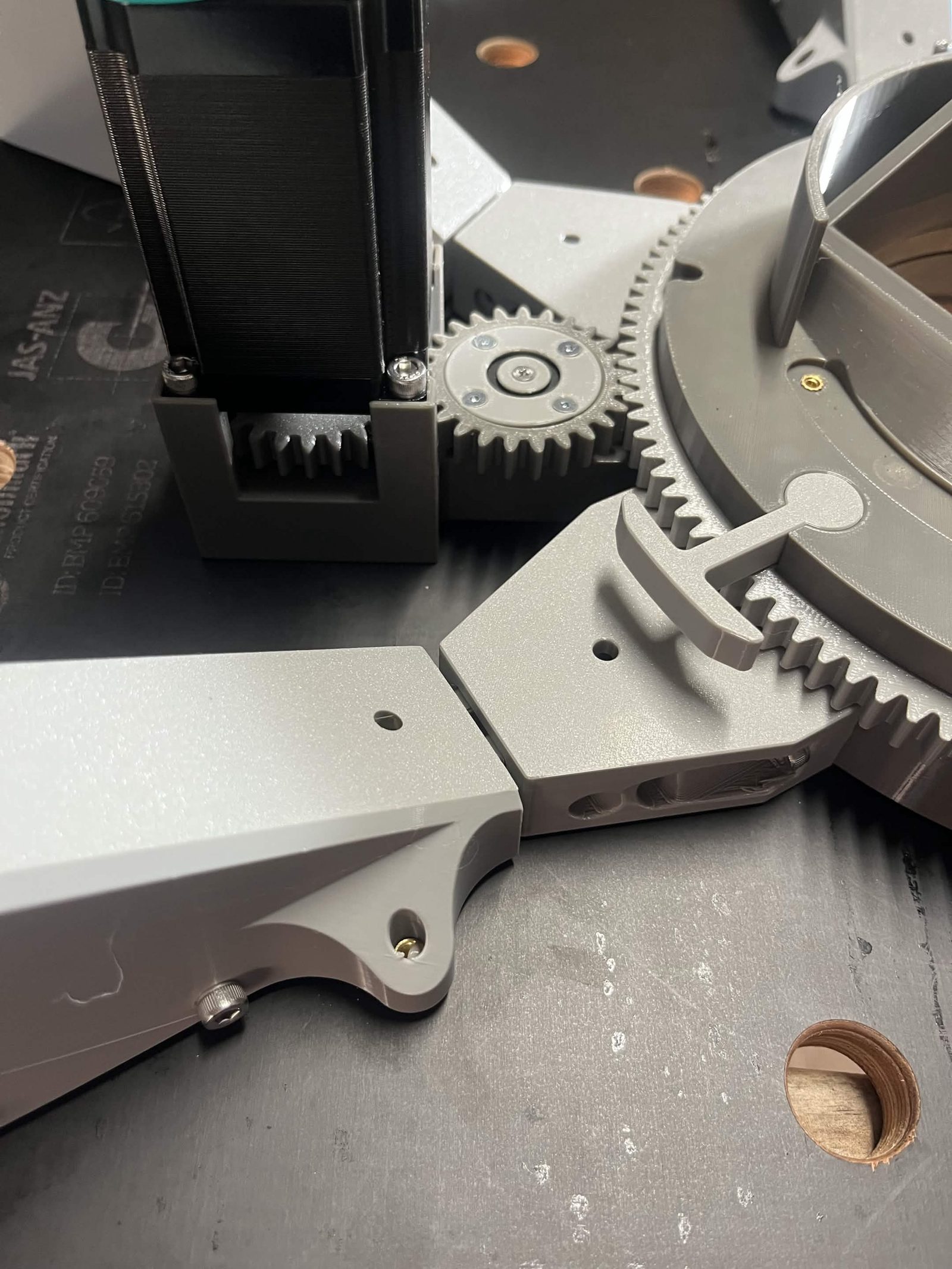
Slot the NEMA 23 onto the Interface NEMA 23 bracket and secure it with four M5 × 12 mm socket / button head screws.
At this point the chute should still rotate, but you will now feel resistance from the stepper motor. Rotate the chute fully in both directions by hand: it should turn smoothly against that resistance, with no catch or scrape as the idler screw head passes the Limit switch hammer.
Step 10 Attach the cable cage top
The cable cage (top, bottom, and clamps) is the channel the ribbon cable (RIB1) runs in while the chute rotates.
Heat inserts first: the Cable cage bracket (cable mount) takes 1 × M3 insert. Press it in before assembling.
Slot the Cable cage top over the Top interface chute mount, with the corners of the hexagon aligning with the Interface brackets. Of the two cage plates, the one that goes on here is the one with the plain round centre hole. The plate with the keyed cutout in its centre hole is the other one, and it goes on at step 12.
Screw the Cable cage bracket (cable mount) to the tail end of the Interface bracket opposite the Limit switch housing, using an M5 × 30 mm socket / button head screw into the M5 heat insert. This clamps the Cable cage top firmly in place.
Screw the remaining Cable cage brackets to the other 5 corners of the Cable cage top with M5 × 30 mm socket / button head screws.
Check the chute still turns after every single screw. The cage jams the rotation easily, and the two usual causes are a hand-cut cage plate and an over-tightened screw. Checking after each one tells you which screw did it; checking at the end of the step only tells you that something did.
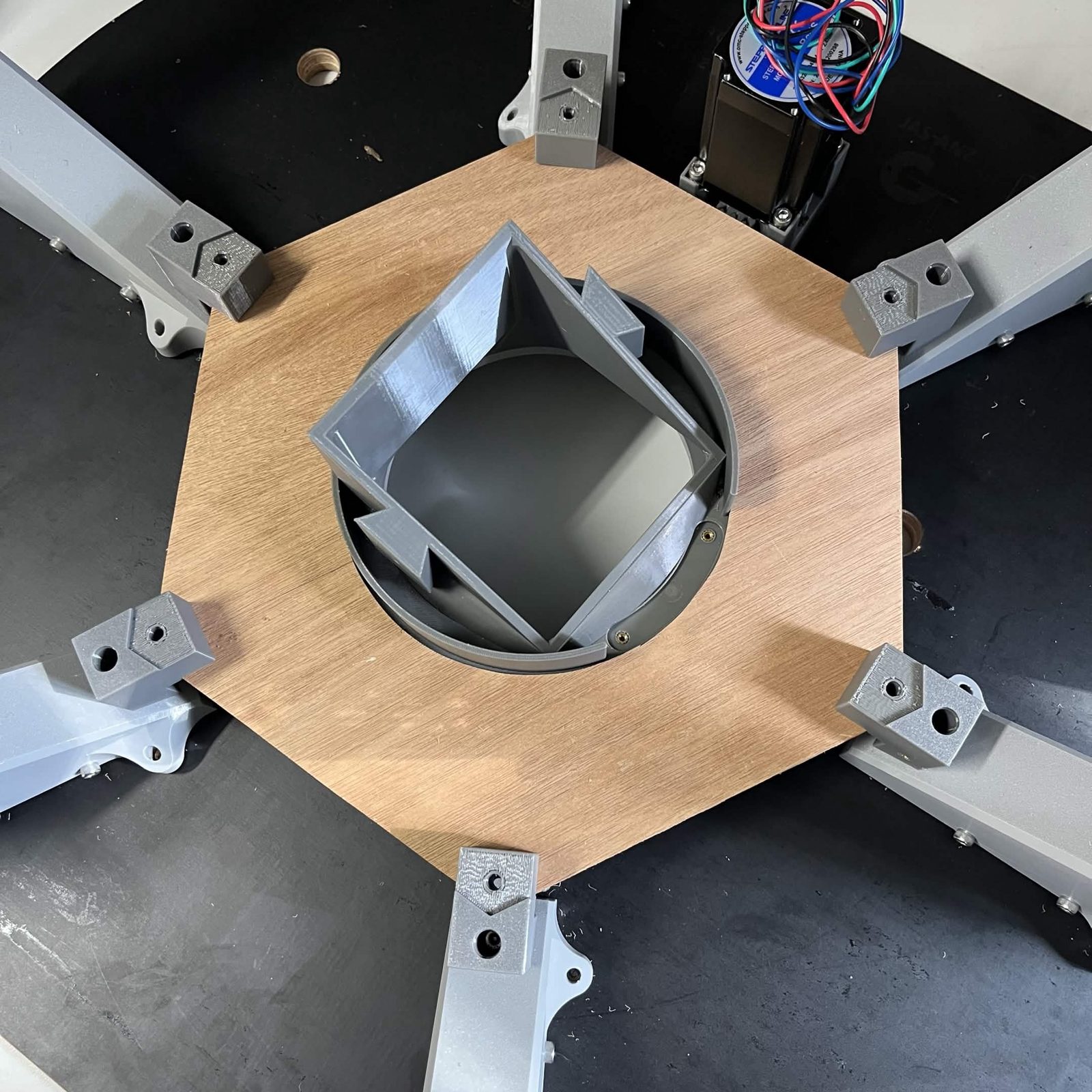
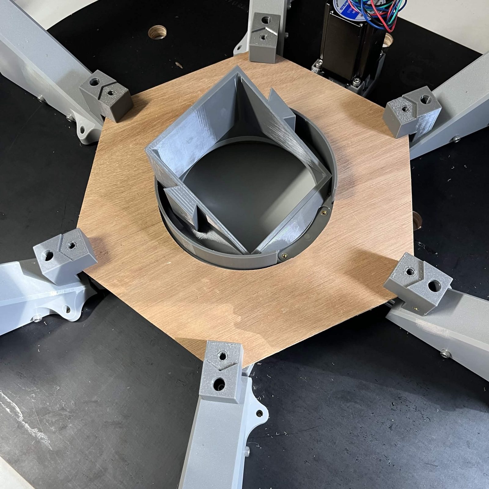
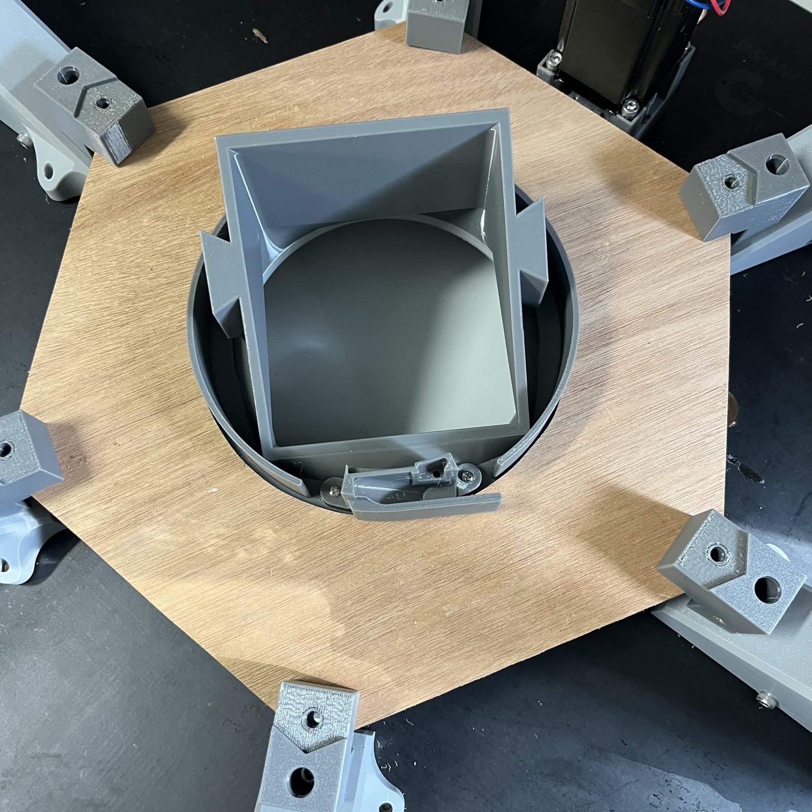
Step 11 Put the ribbon cable (`RIB1`) in the cable cage
Place an M3 nut into the bottom of the Cable clamp (outer) (the video skips this), then push it into the recess in the Top interface chute mount. Fasten it with two M3 × 12 mm socket / button head screws.
The nut is not captive: nothing holds it in the pocket until the clamp is pushed into the recess. Check it is lying flat on the bottom of the pocket and keep that face upwards while you mount the clamp. If it falls out or sits skewed, the long screw later in this step has nothing to start on, and you cannot get at it once the clamp is bolted down.
Rotate the chute until it hits the limit switch.
Fold your IDC ribbon cable (RIB1) around the Cable clamp (inner), following the guides on the clamp. Slide the cable and clamp together into the Cable clamp (outer), leaving a tail to connect to the chute above.
Leave about 80 mm (3 in) of tail, measured from where it leaves the clamp, which is what it takes to reach the layer adapter board on the chute core that sits on top of this assembly.
The connector goes on pins up. You should be able to see into the connector from above when the tail is lying where it will sit; if it is facing down at the bench, the cable is on the wrong way round. Getting this wrong is expensive: three steps have to come apart to turn it over.
Guide the rest of the ribbon cable (RIB1) around the side of the Top interface chute mount, in the direction the chute can rotate, back to the Cable cage bracket (cable mount).
Screw the Ribbon cable clamp lightly to the Cable cage bracket (cable mount) with one M3 × 12 mm socket / button head
screw, clamping the ribbon cable (RIB1) between the two. Leave the clamp standing slightly off the bracket face rather than pulling it down hard, so the ribbon is not crushed.
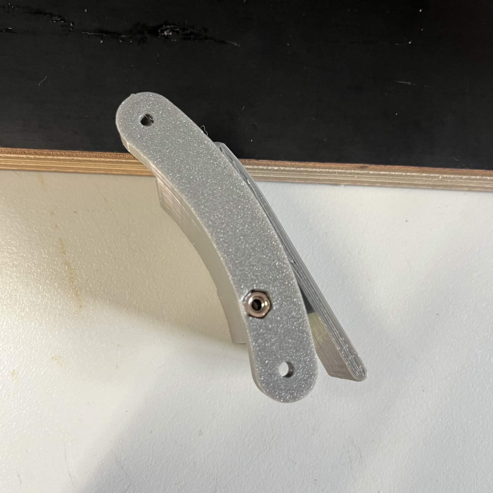
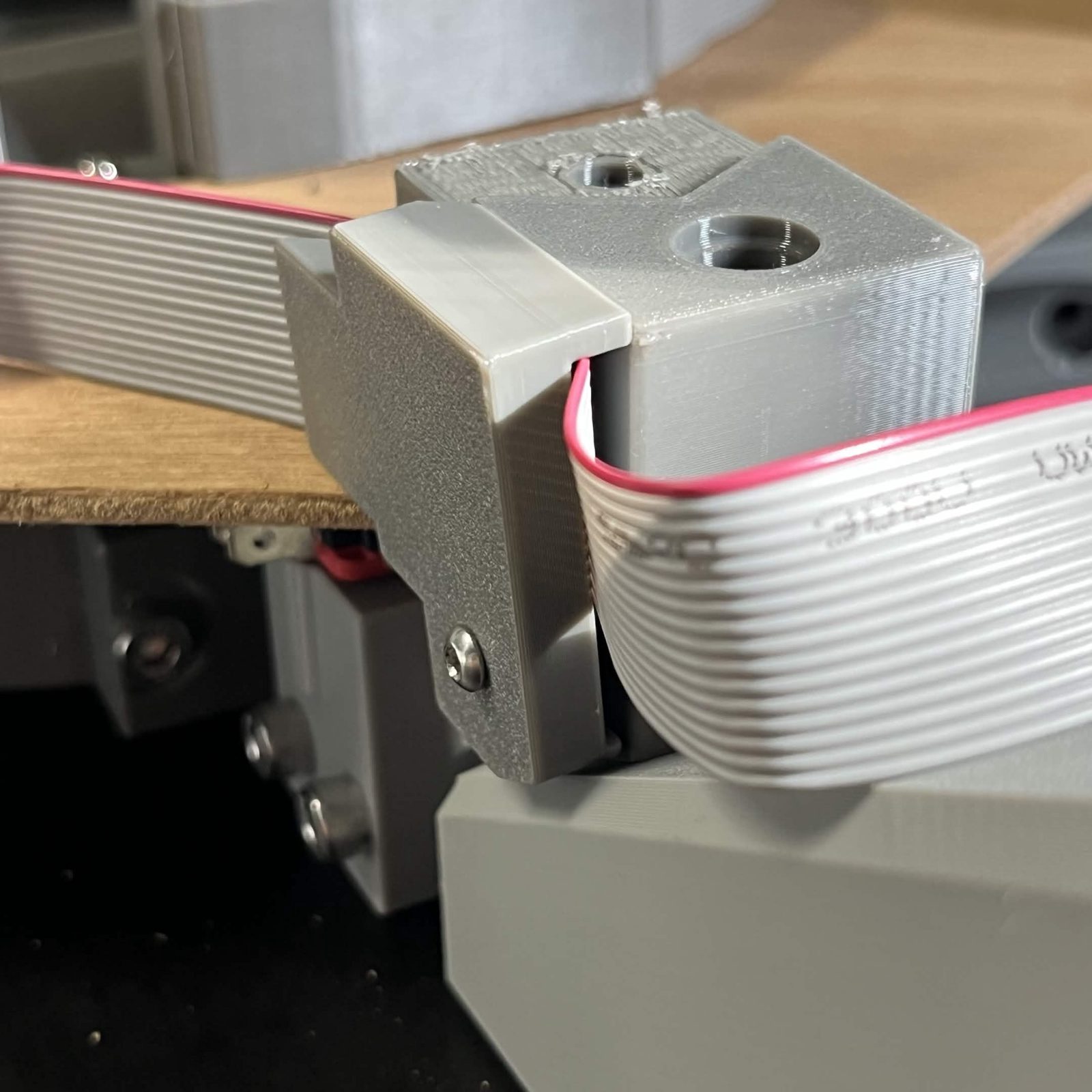
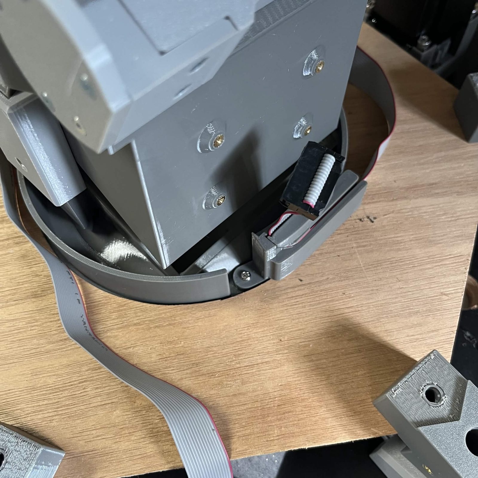
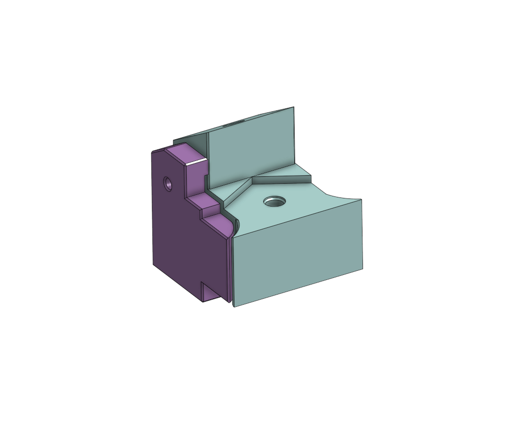
Check that the chute can rotate fully to the limit switch in both directions, then tighten the Ribbon cable clamp screw. Use a long M3 × 40 mm flat head screw through the Cable clamp (inner) into the M3 nut in the bottom of the Cable clamp (outer) to secure that end.
Step 12 Attach the cable cage bottom
Place the Cable cage bottom over the Top interface chute mount. This is the plate with the keyed cutout in its centre hole, the pocket that bulges outward on one side. Use 6 M5 × 35 mm flat head screws and M5 nut s to clamp the Cable cage bottom, Cable cage top, and Cable cage brackets together.
After this step the chute should still rotate to each of its limits. Same as step 10: check after each screw rather than at the end, and back a screw off rather than forcing the chute past a tight spot.
Step 13 Attach the framing
Install four T-nuts and their M5 × 20 mm socket / button head screws in each Interface bracket, then fit in an extrusion piece F (Interface vertical support), 274 mm. The framing cut list has every length on this page. Leave 165 mm of the extrusion standing out of the bracket, measured from the edge where it exits to the free end. Step 14 shows the corner in section.
Slide an Interface spacer onto each piece of extrusion, with the lip at the top facing toward the center of the assembly.
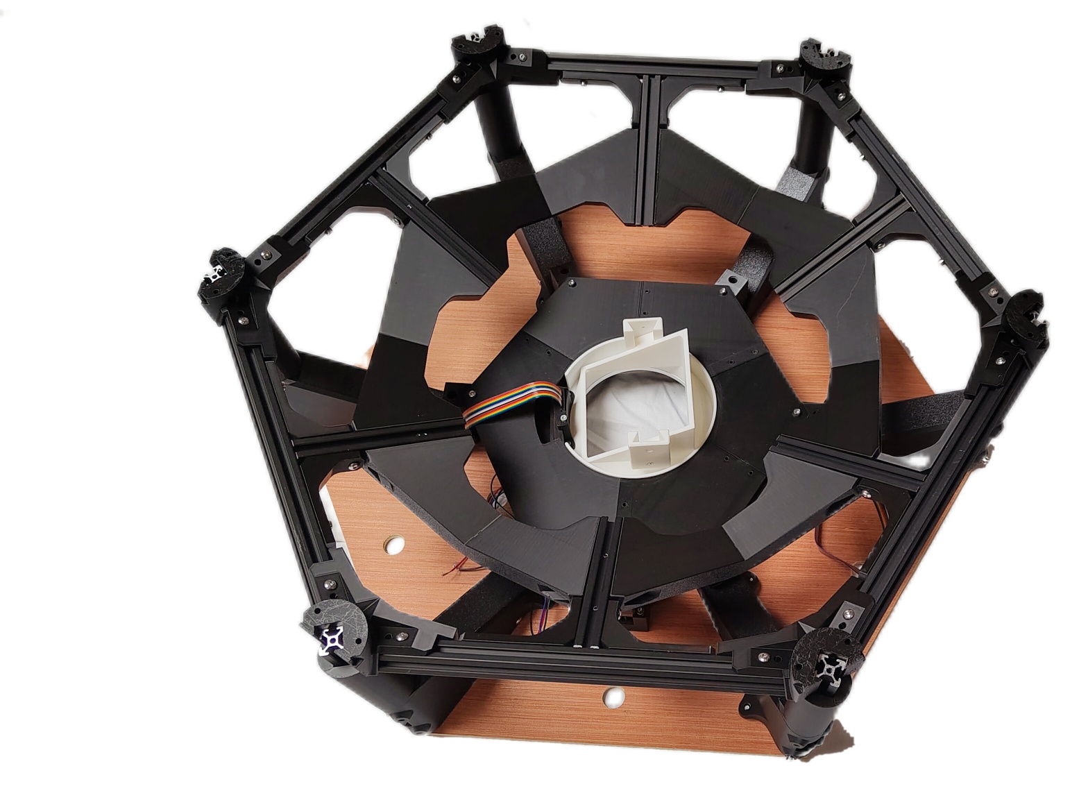
Build a hex frame, then place it onto the interface assembly.
Roll 6 T-nuts into this hex frame's own extrusions while you are here, 2 each for the PSU box, the control board housing and the Orange Pi housing. All three bolt onto this frame later, and the layout render on installing the electronics shows where each one sits. Their screws and the rest of their hardware are listed on those pages, not here.
No problem if you forget them. The T-nut this build specifies is the spring-loaded roll-in kind, which drops into the slot anywhere along its length, so these six can still go in later without taking the frame apart.
Attach an External bracket cover to each of the External bracket sides, then fasten each one with 2 M5 × 16 mm socket / button head screws into the holes at the base of the External bracket sides, bracing against the extrusion. These holes run parallel to the extrusion profile, and the screws are self-tapping. There is no External bracket — bottom vertical at this joint; see step 14 for what's different here.
Step 14 How the interface joins the top layer
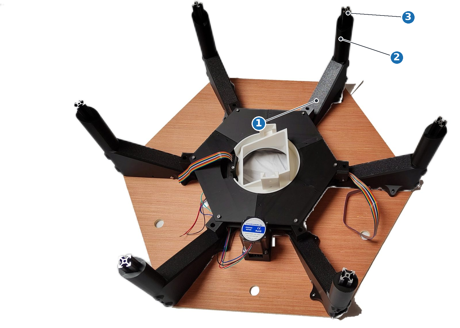
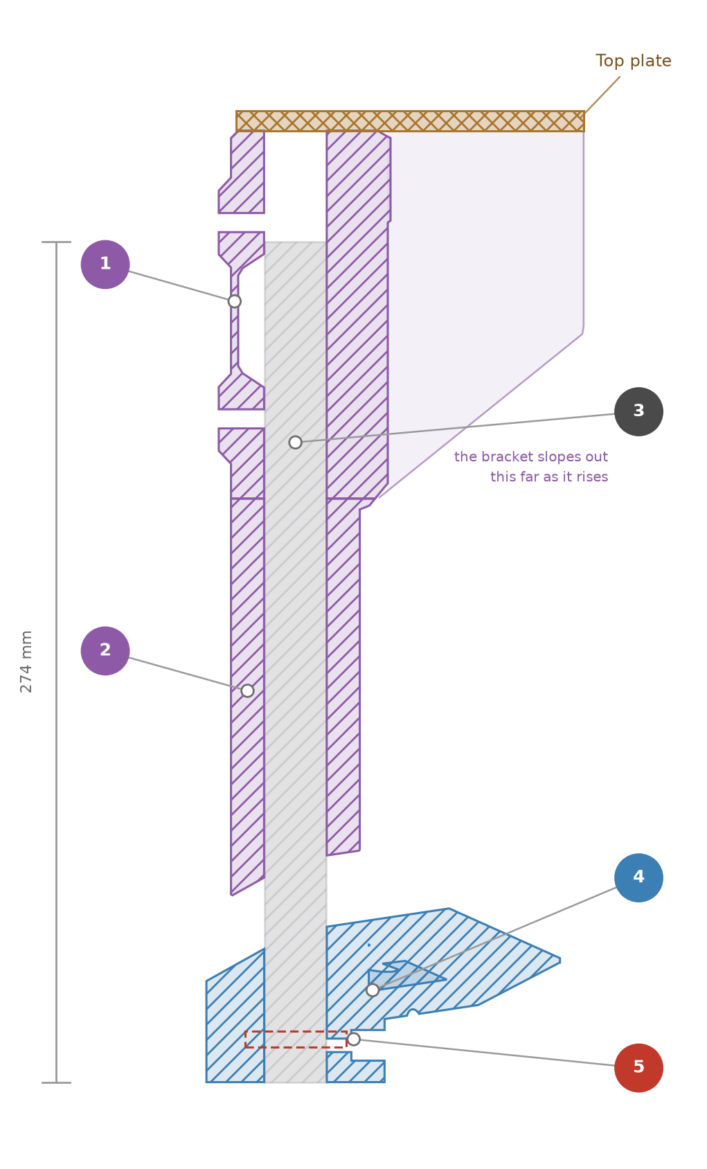
This joint is not the same as the one between two layers, so it is worth naming what is different. There is no External bracket — bottom vertical and no flange here, and therefore none of the vertical screws that hold one layer to the next. Piece F is instead gripped at the interface end and clamped at the layer end, and it is sleeved the whole way between them, so no extrusion shows on a finished machine.
The numbers on the photo and the drawing:
- Interface bracket, one per corner, a 120 mm channel around the extrusion. Piece F is held in it by 4 M5 × 20 mm socket / button head screws into T-nuts , the only place in the framing where a vertical is fixed with T-nuts rather than a self-tapping screw.
- Interface spacer, a 129.7 mm sleeve, slid onto the extrusion with its lip at the top facing the centre. It takes no screws and simply sits between the bracket and the layer's collar.
- Piece F, 274 mm cut (280 mm in CAD) against a layer's 154 mm, so the interface sits 120 mm further above the top layer than one layer's spacing.
- The top layer's External bracket — side, with its cover, exactly the collar any layer has.
- Two M5 × 16 mm socket / button head screws at the base of that bracket brace it against the extrusion, the same screws and holes a layer's own vertical gets. Nothing else fastens the interface to the layer.
Piece F does not reach the top of the Interface bracket, and it comes nowhere near the top plate. The 165 mm standing out of the bracket in step 13 is what sets where it sits.
The finished result
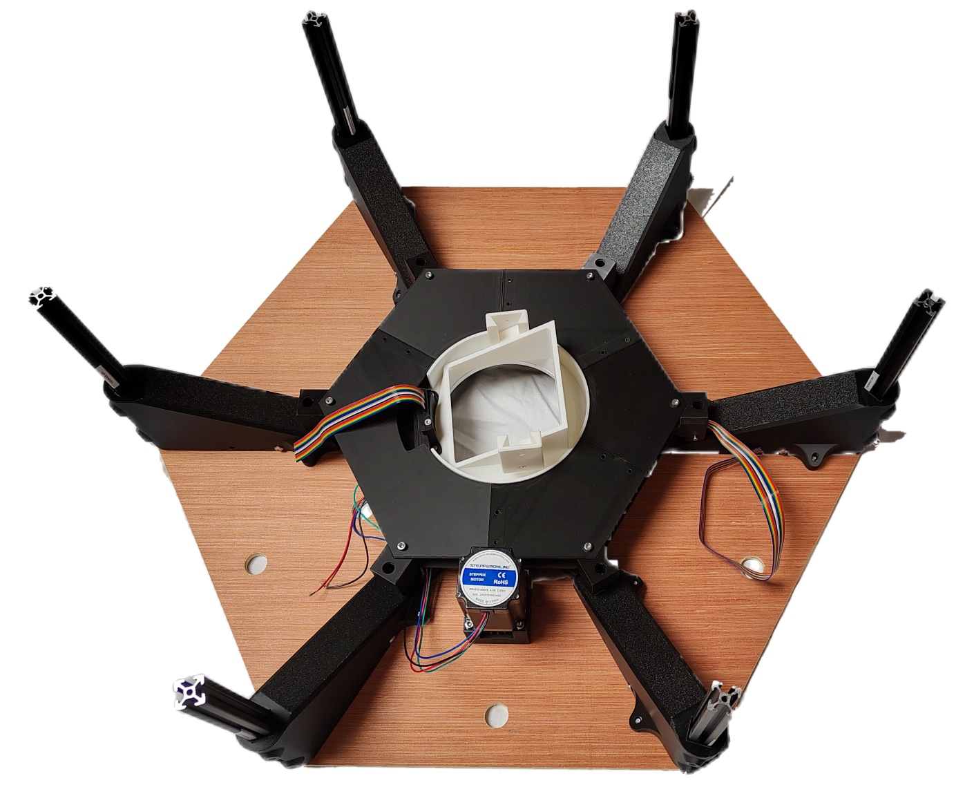
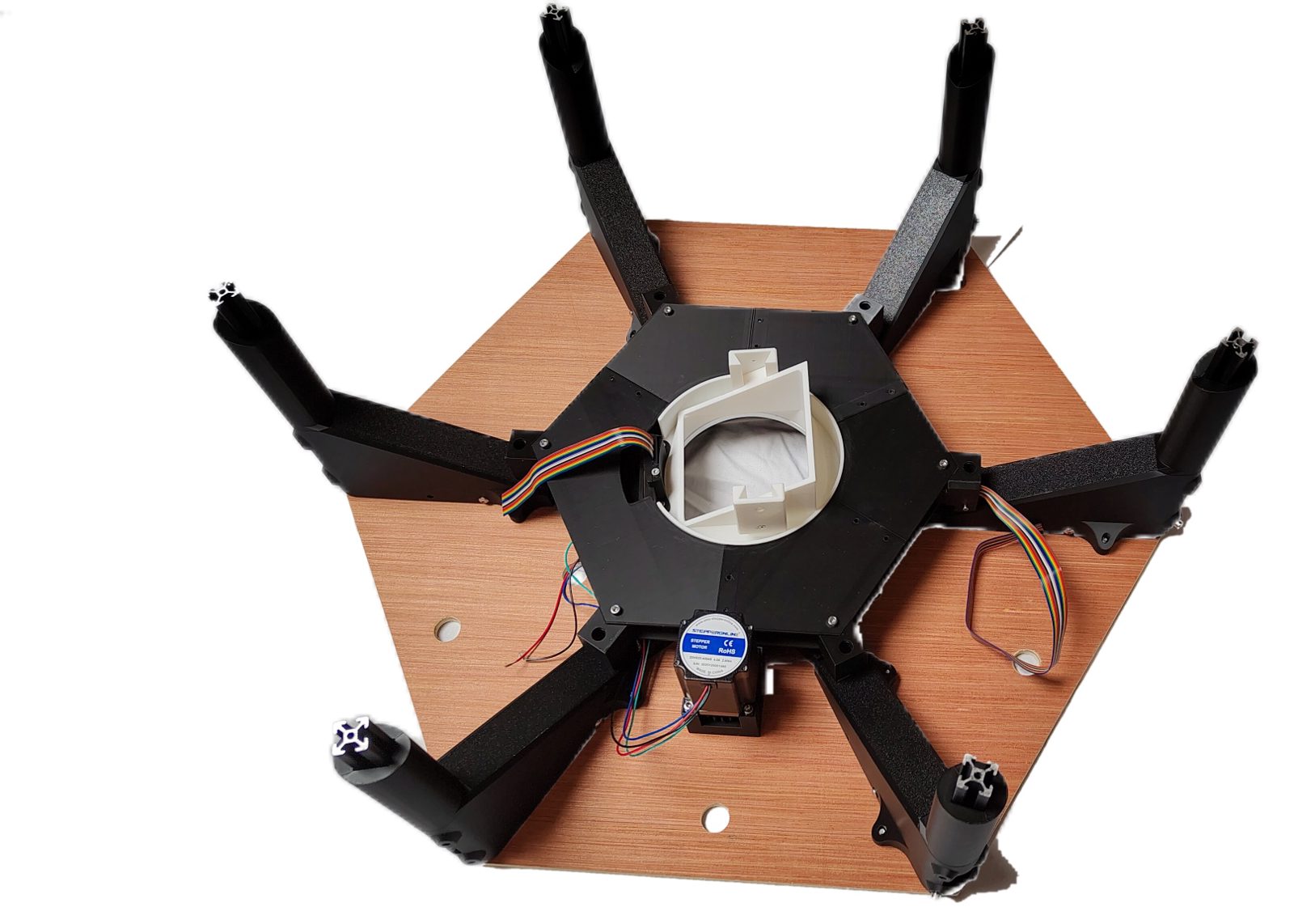
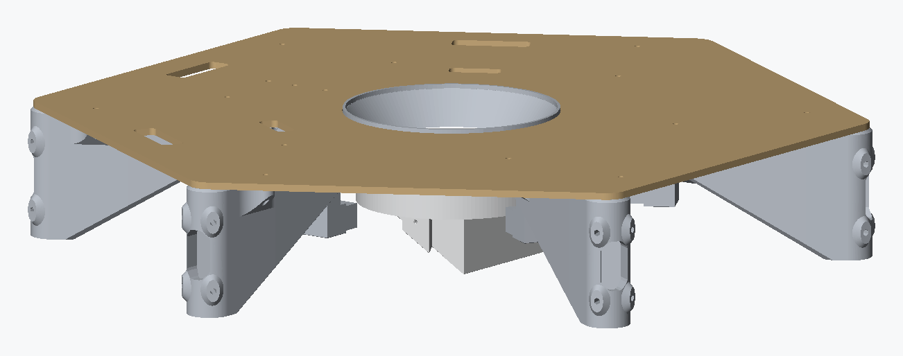
The top plate, its six bracket mounts and their extrusion, the rotating chute mount and its gear train, and a hex frame closed onto the bottom of the verticals.
The Distribution page contains the instructions for the entire assembly, and is where you should return once you're done here.