
Feeder — Arranging C-channels
Arranging C-channels
How-to guideThe stands the four C-channels sit on, the heights they set, and the order the channels go onto the top plate.
Parts needed
Printed parts
- 3×
- 3×
- 3×
- 9×
Aluminum extrusion (2020)
- 3× 228mm2020 aluminum extrusion, 228 mm, piece J on the framing list.
Four finished channels go on this page. It does not build any of them.
One bulk channel, C1. The faceted rotor in, and the Bulk cap on the stator.
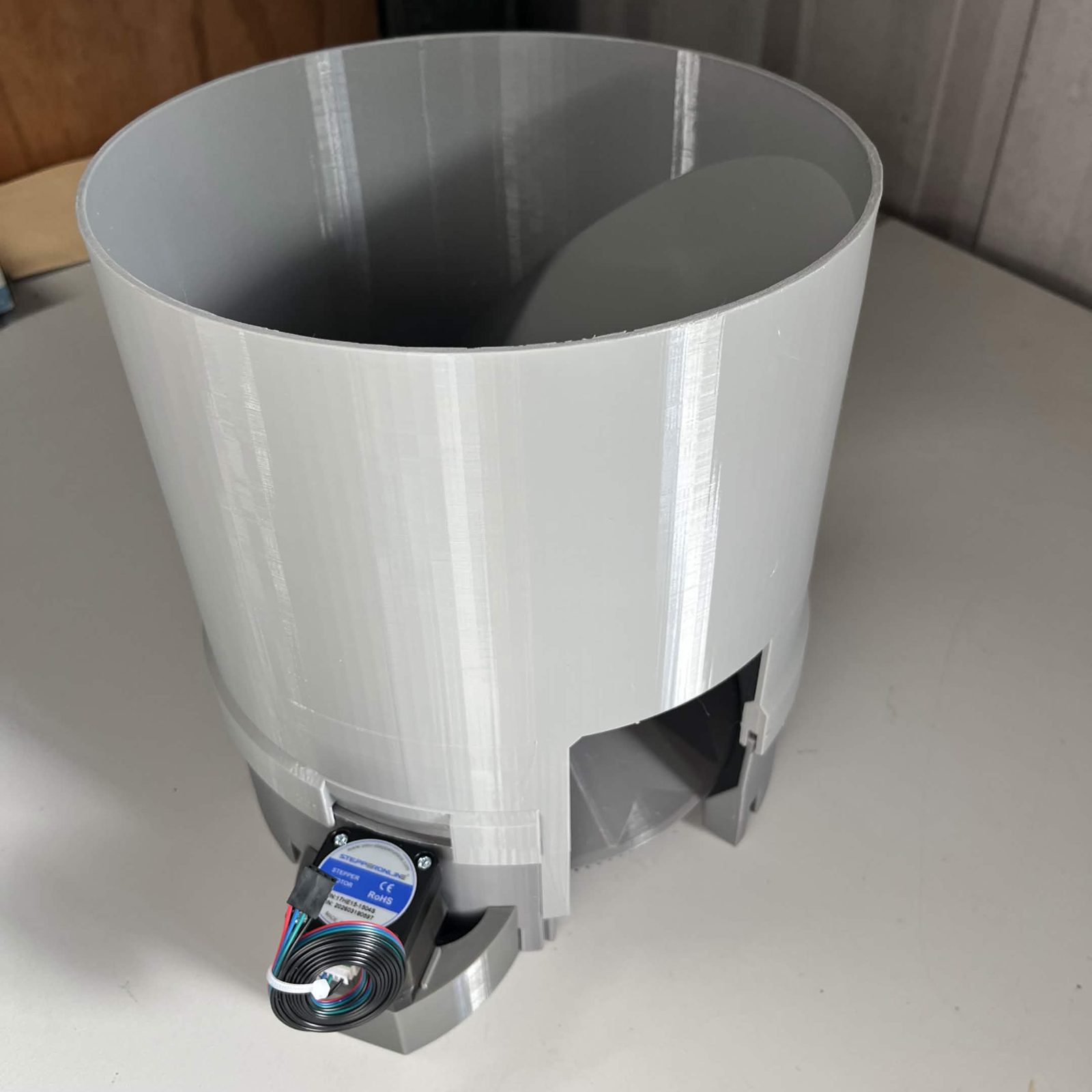
Two feeder channels, C2 and C3. The faceted rotor in and an output guide on. They are the same build; only the height differs, and that is set here.
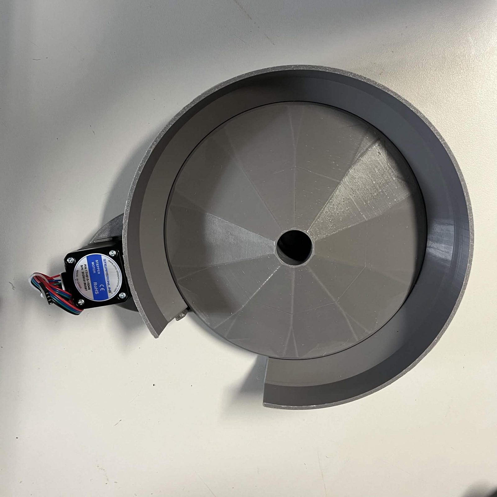
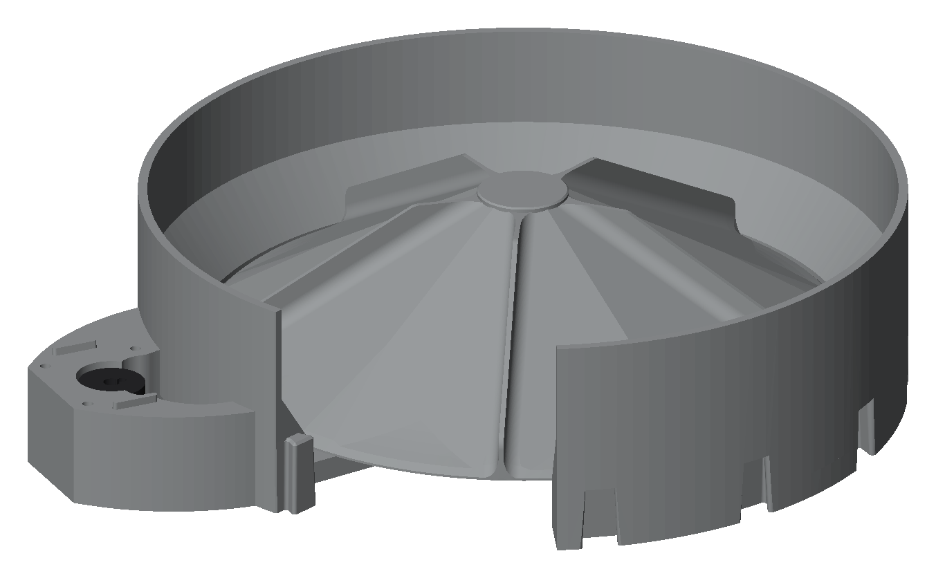
One classification channel, C4. The finned rotor, capped. It is the only one of the four with no support structure of its own.
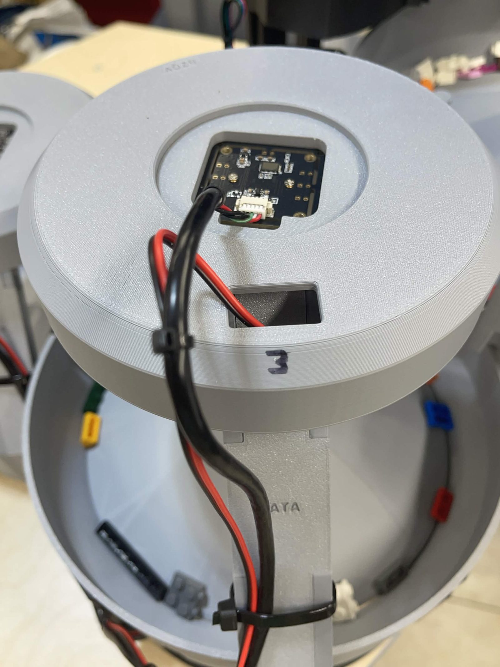
Three camera lamps. Two feeder lamps and one classification lamp. C1 takes none.
The four stand at different heights, so a part cascades from one to the next under gravity and arrives at the interface singulated.
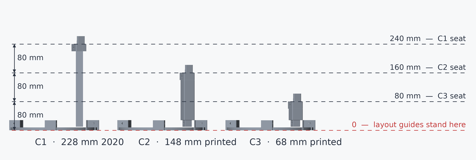
C1, C2 and C3 each stand on their own three-legged stand, and the legs are the only thing that differs between them: their lengths are what set the drop from one channel to the next. C4 has no stand at all. It sits flat on the top plate, located by C3's layout guide, and it goes in before the other three.
Steps below use the names the software uses, C1 to C4, in the order a part travels: C1 highest, C4 lowest.
Step 1 Build C1's stand
The tallest one. Three moves, and they are the same three on every channel:
- Put a layout guide down flat, sockets up.
- Stand the three legs in it. C1's are C-channel 1 support leg, 228 mm of 2020 extrusion, piece J on the framing list. They are held by their own weight.
- Drop a dovetail adapter over the top of each leg. The adapter's flat top face is what the channel sits on, not the tip of the tang above it.
The channel itself goes on later, in step 6, once all three stands are laid out and C4 is in.
How the 2020 sits at each end. Into the layout guide it slides with a firm fit. At the adapter it is only braced on three sides. Tip: BrickCycleAlice.
The stands are designed to be screwless. Every joint is gravity or friction, so no screw is required, none is in the parts list or the count, and nothing takes a heat insert.
Pinning a stand is optional. Each leg joint has a cross hole for it, at the foot where the leg stands in the layout guide and at the top where the adapter caps it. Line the holes up and put an M5 × 16 mm socket / button head through the wall of the guide's socket, or of the adapter, into the leg: it cuts its own thread in a printed leg. That is one screw per leg end, 6 for a stand. C1's legs are extrusion, not printed, so each of those needs an M5 T-nut in the slot for the screw to pull against, 2 per leg. C1 is the one worth pinning, because it carries the bulk bin. They are on the assembly tree in the parts calculator, marked optional and left out of every total.
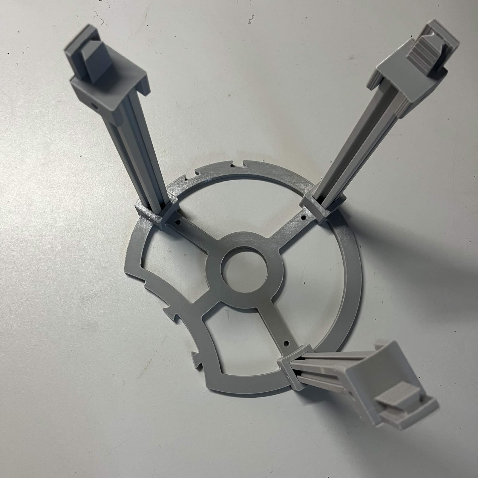
Step 2 Build C2's stand
The same three moves, with three C-channel 2 support legs, printed.
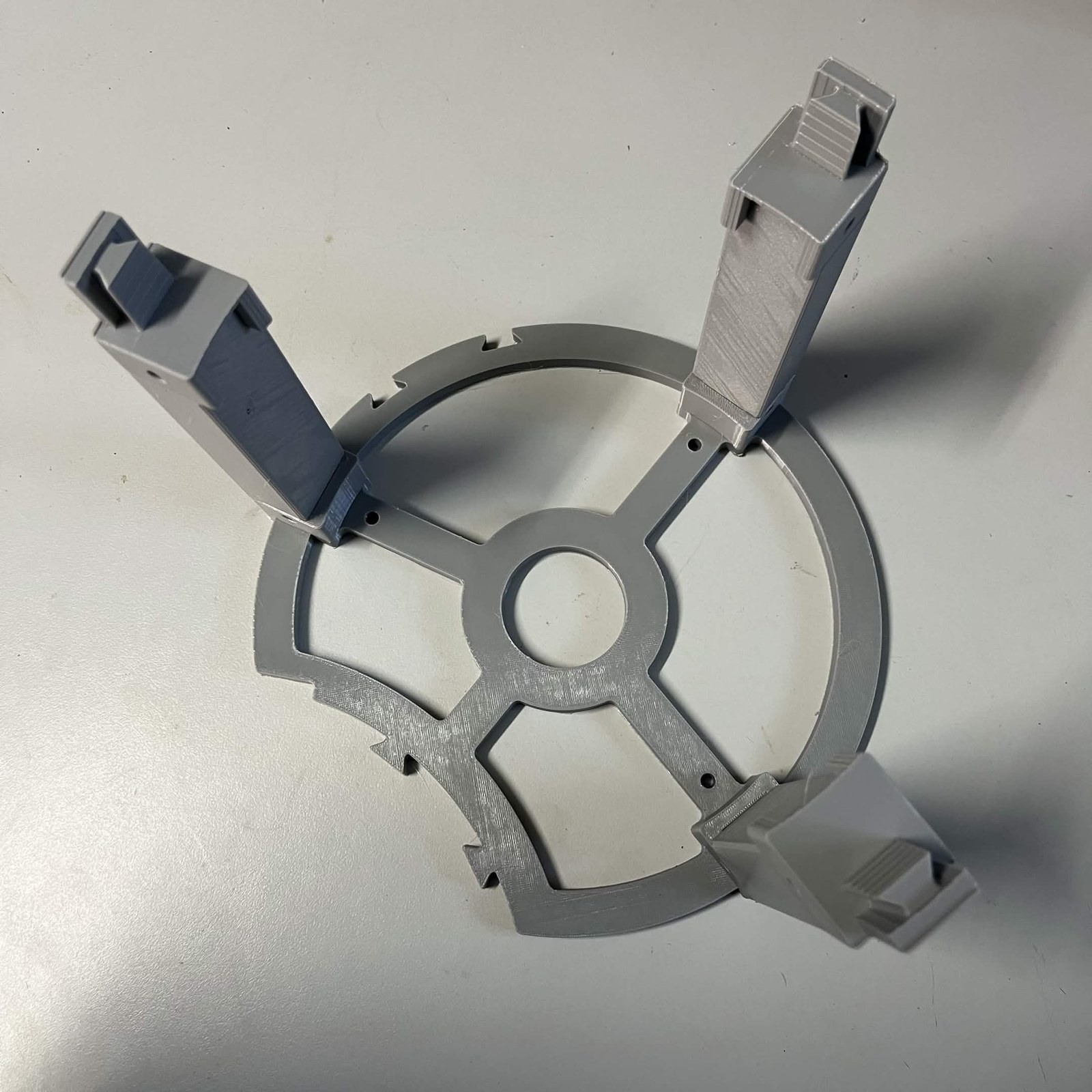
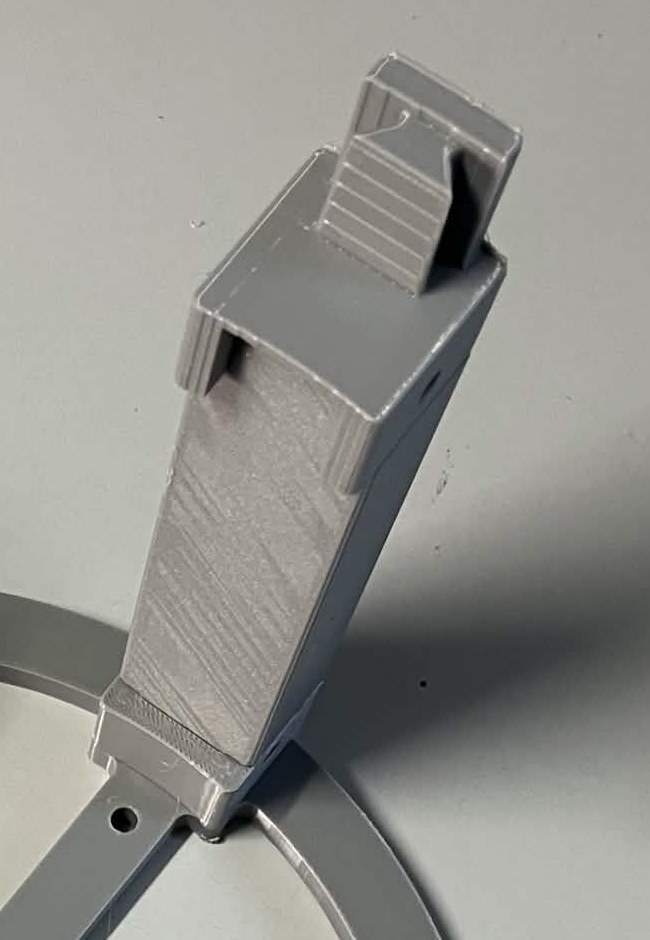
Step 3 Build C3's stand
The same again, with three C-channel 3 support legs, printed.
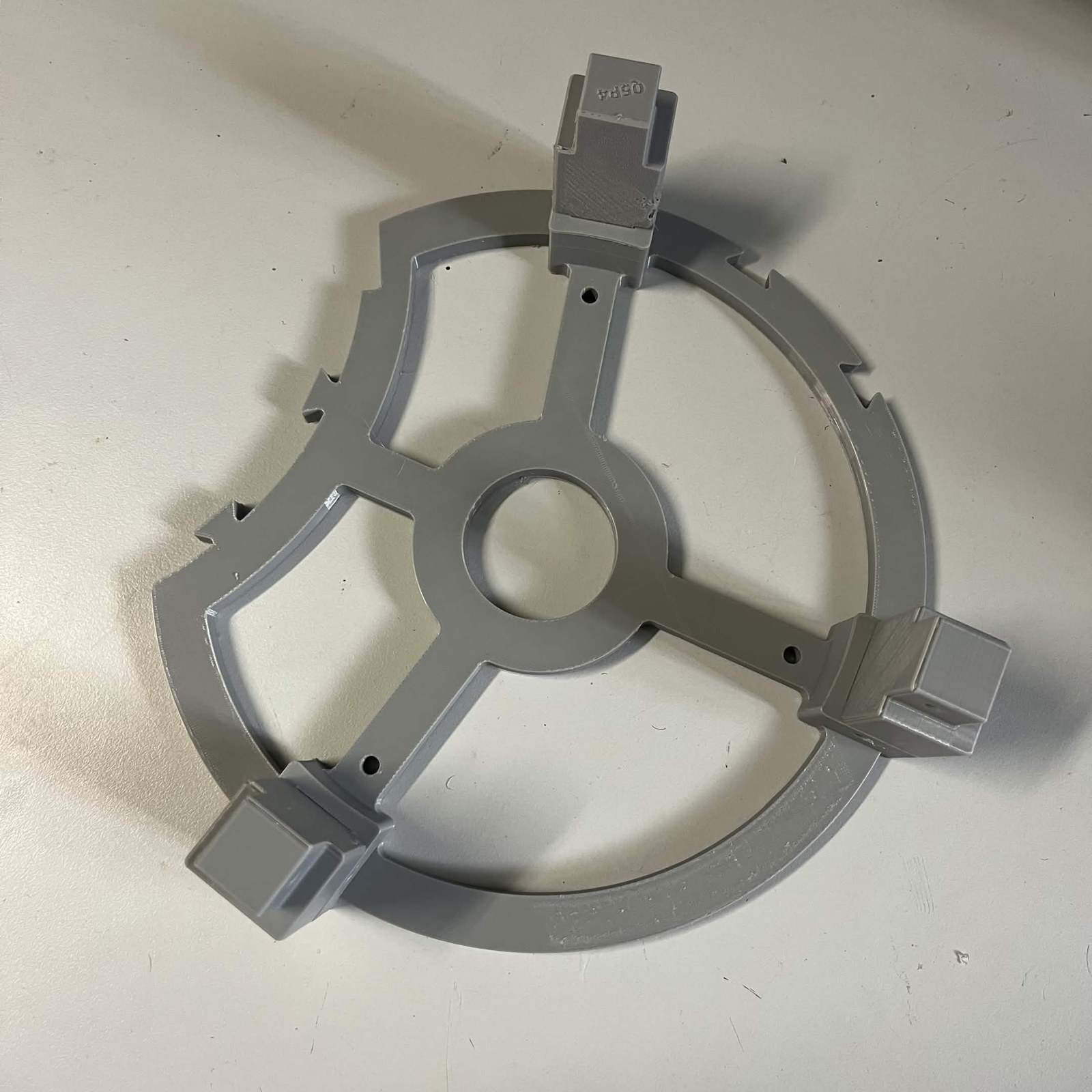
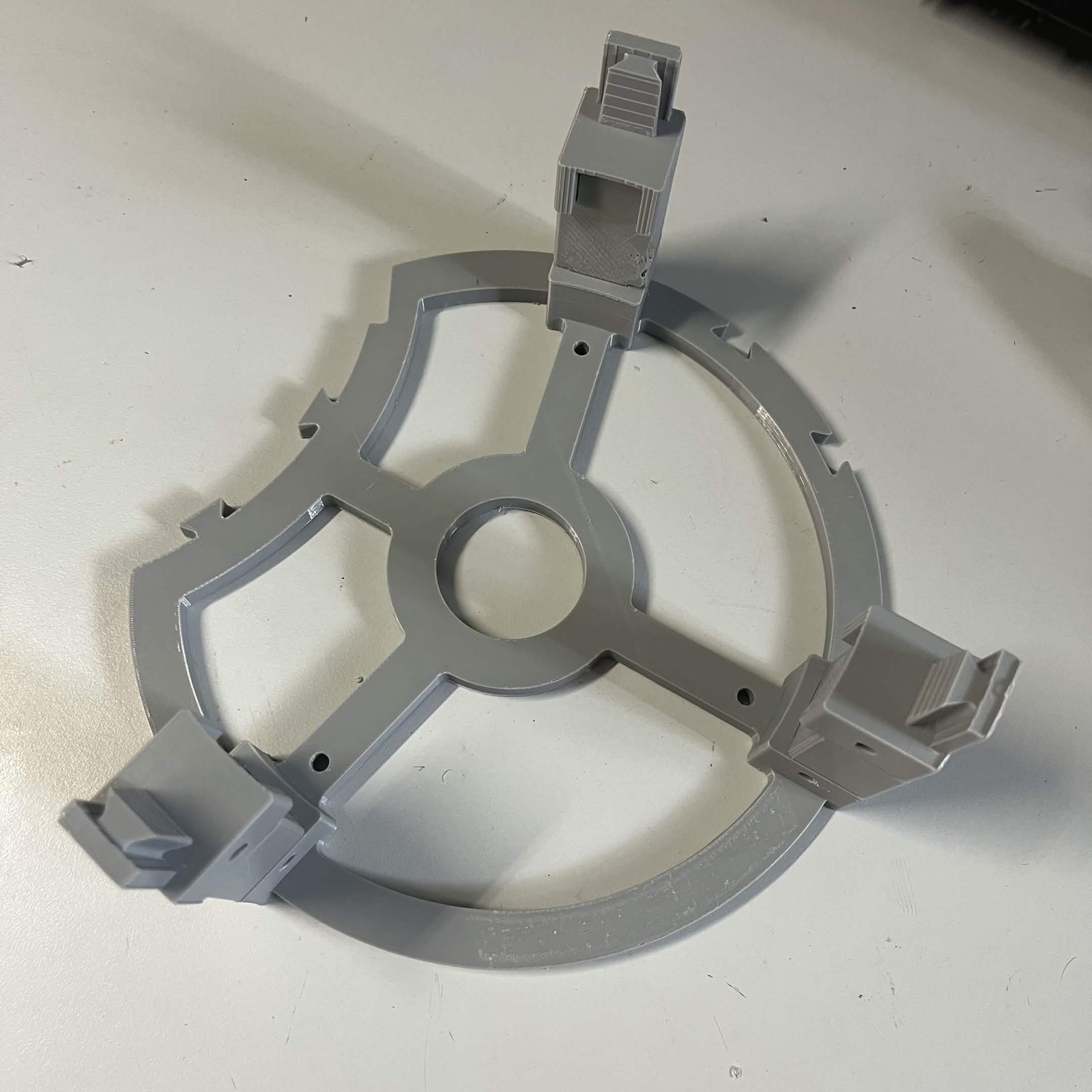
Step 4 Lay the three stands out
Put all three on the top interface's top plate. The drop between channels comes out of this on its own. You do not measure it: each channel has its own leg, and standing all three guides on the same flat surface sets the rest.
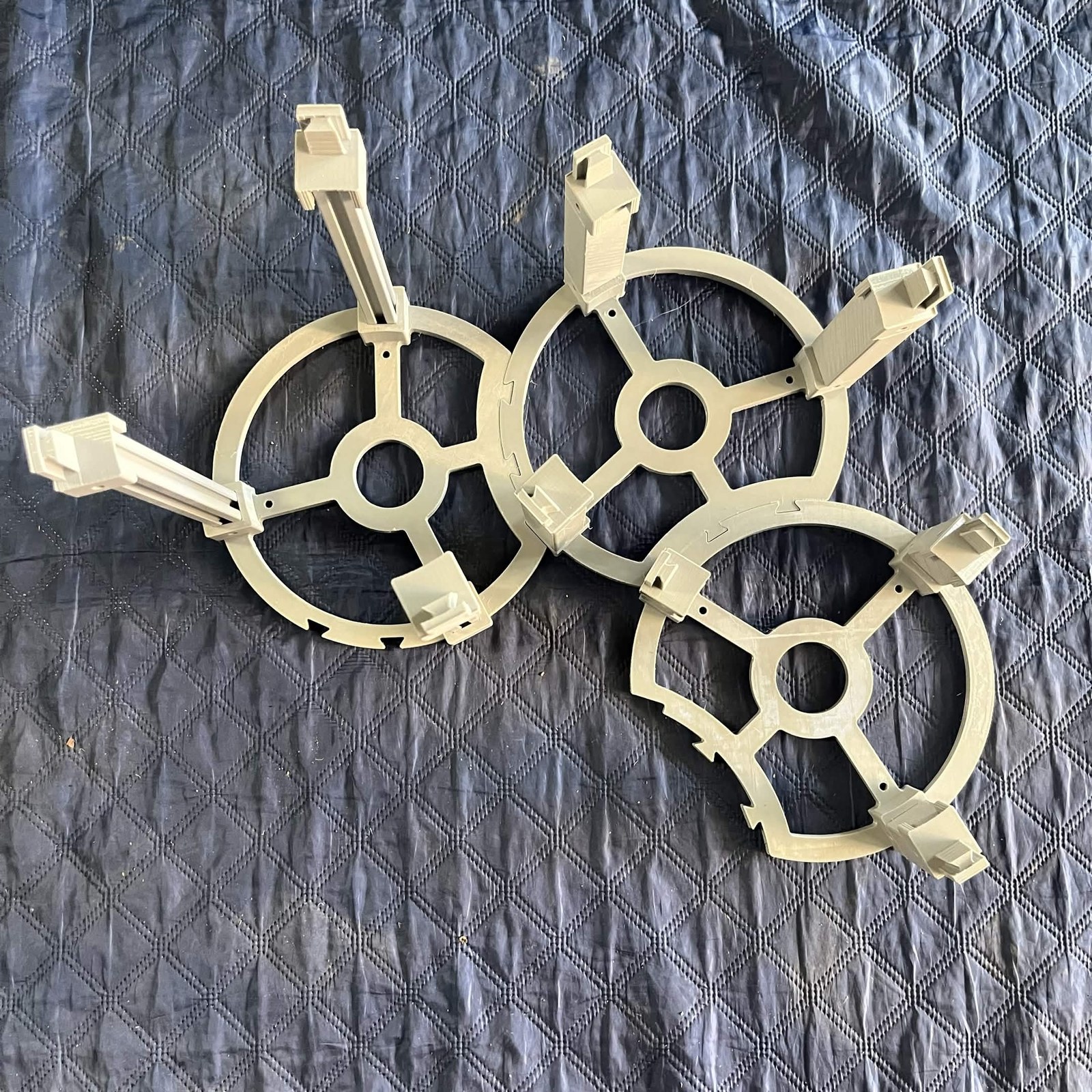
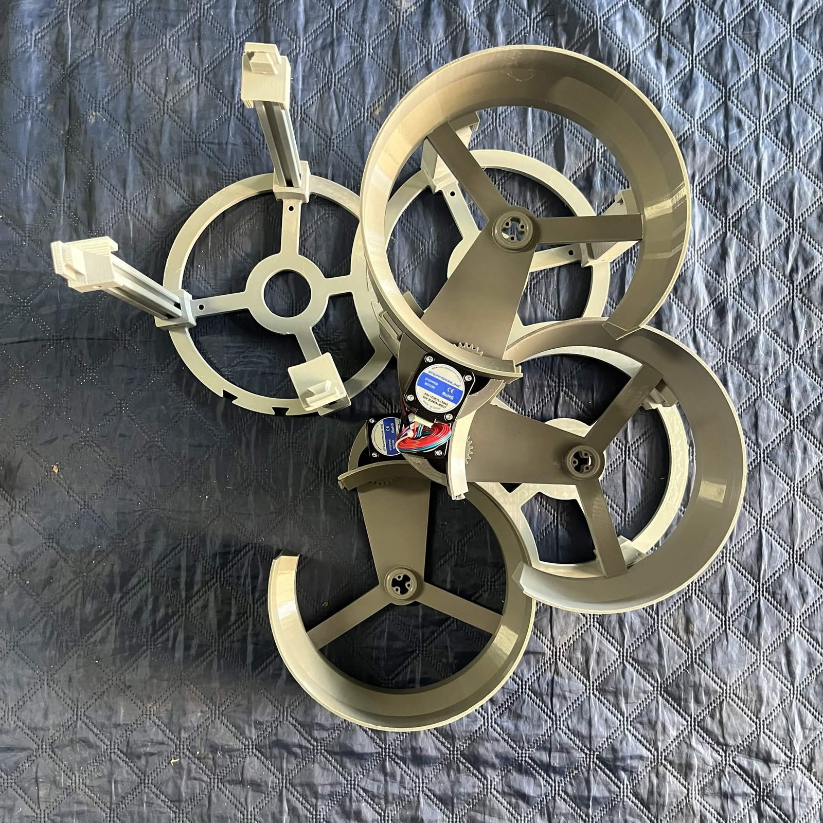
Clock all three the same way, with the steppers toward the centre of the guides. Nothing in the STLs says which of a channel's three legs sits under the motor — the layout guide is exported on its own — so this is how it is actually built. Tip: BrickCycleAlice.
Don't add more drop than this to fix bouncing. A part is supposed to arrive at the next rotor with most of its energy gone; a bigger drop makes pieces bounce further and re-clump, which is the problem the cascade exists to solve. If parts are riding round a channel instead of leaving it, that's the output guide's job, not the height's.
Step 5 Install the classification channel
C4 goes in first, before the three above it, and it takes no support structure of its own — no layout guide, no legs, no adapters. It sits flat on the top plate and slides onto the layout guide that C3 stands in.
The top plate itself has no mount holes for a C-channel, so nothing bolts down here.
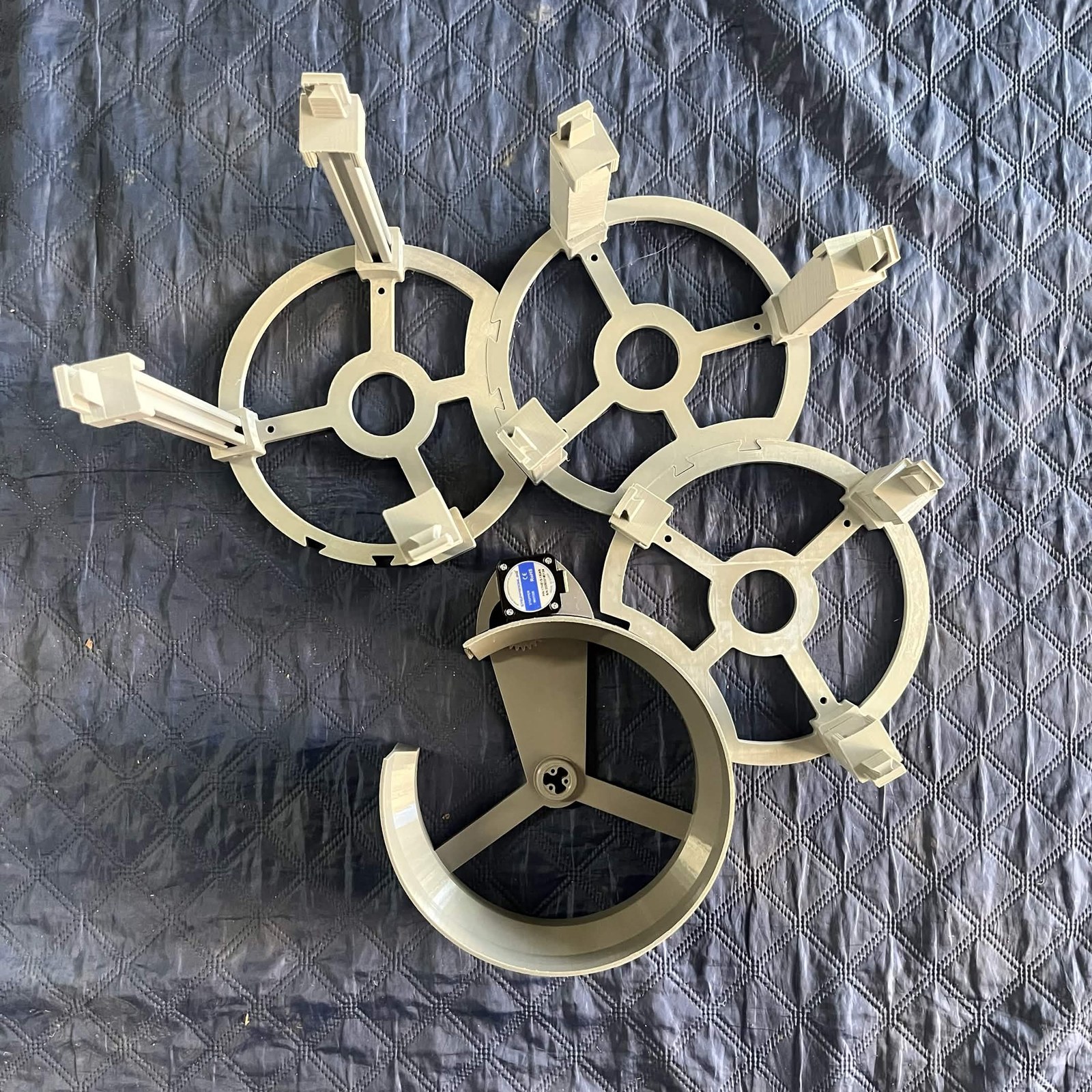
Step 6 Install C1, C2 and C3
Now the other three drives go on their stands. Lower each one onto its three dovetail adapters so the tangs engage it from below. It's a friction fit; the channel's own weight holds it.
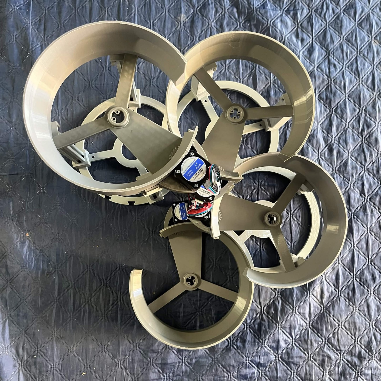
The drive in the photograph below has no rotor in it, which is the only way to see the joints; yours arrive from the channel pages with theirs already in. It also shows the clocking from step 4: every stepper ends up in the middle of the group.
Step 7 Hang the camera lamps
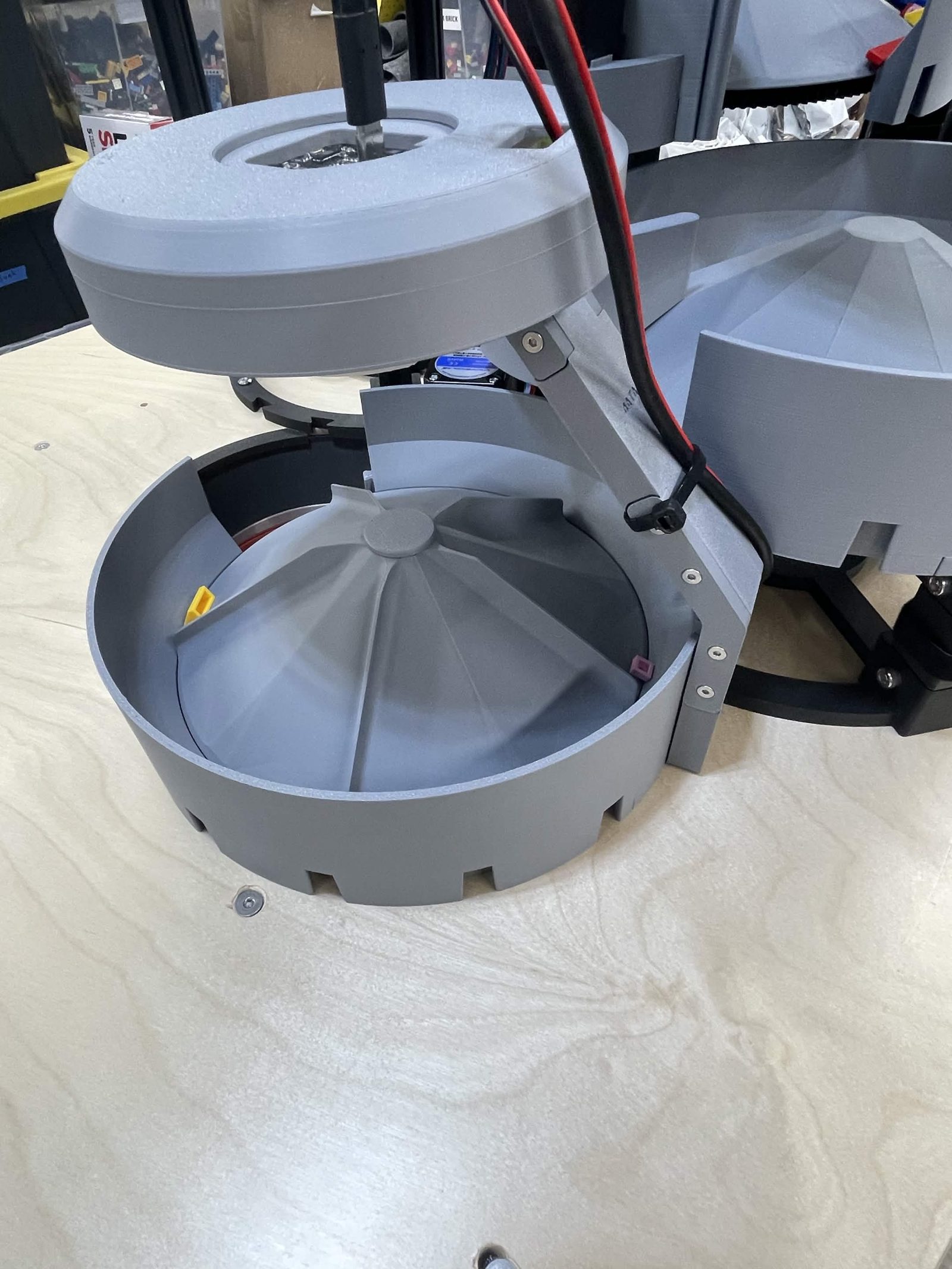
One camera lamp on C2, one on C3 and one on C4. C1 takes none, because it's fed in bulk and nothing reads vision off it.
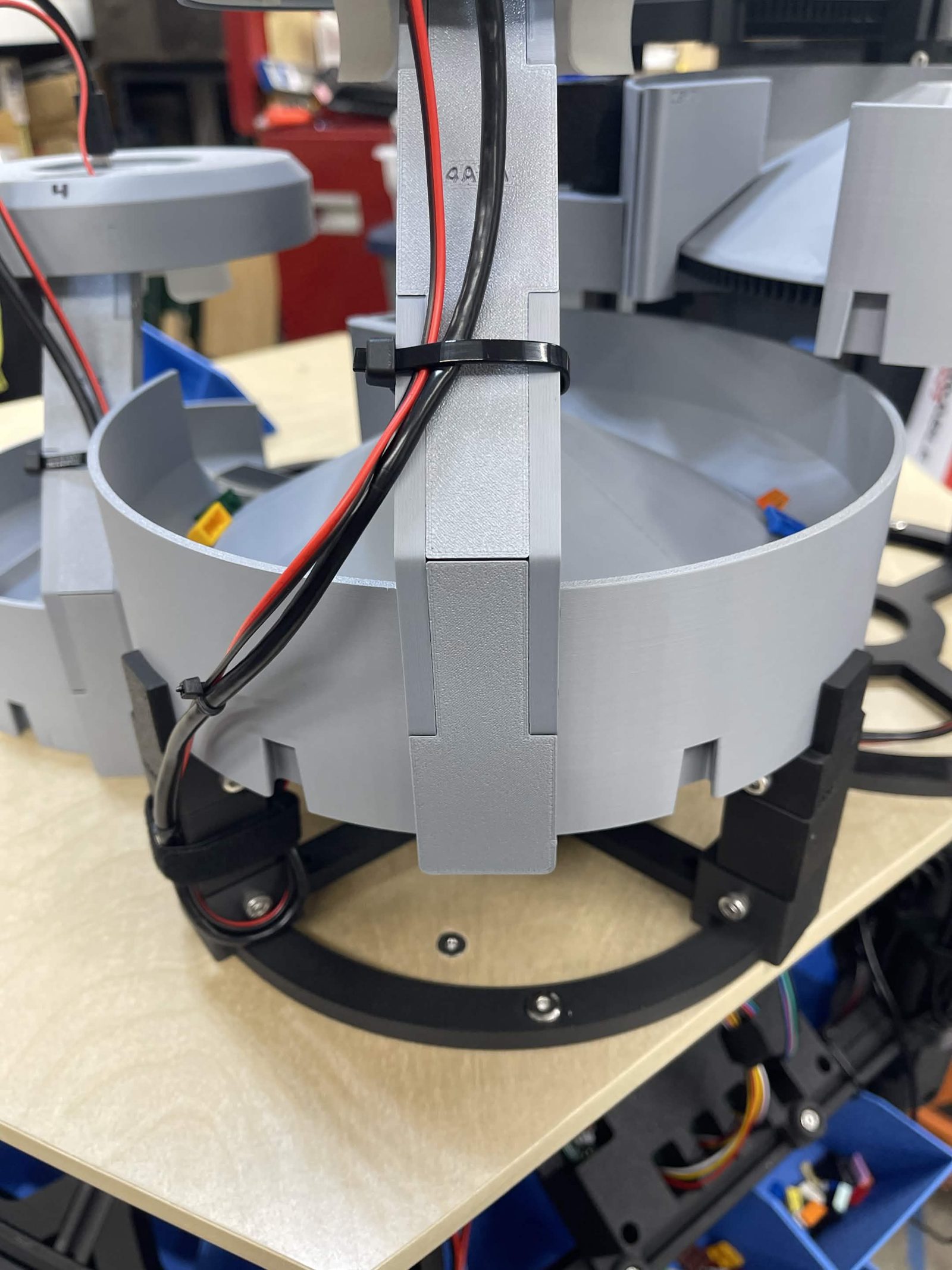
Which dovetail the arm goes in. The outside of every channel wall carries a row of dovetails, evenly spaced all the way round except where the exit opening interrupts them. Count anticlockwise from the exit, seen from above, taking the first dovetail past the exit as number 1:
- C2 and C3: the 5th.
- C4: the 8th, which is the last one before the channel above covers the wall.
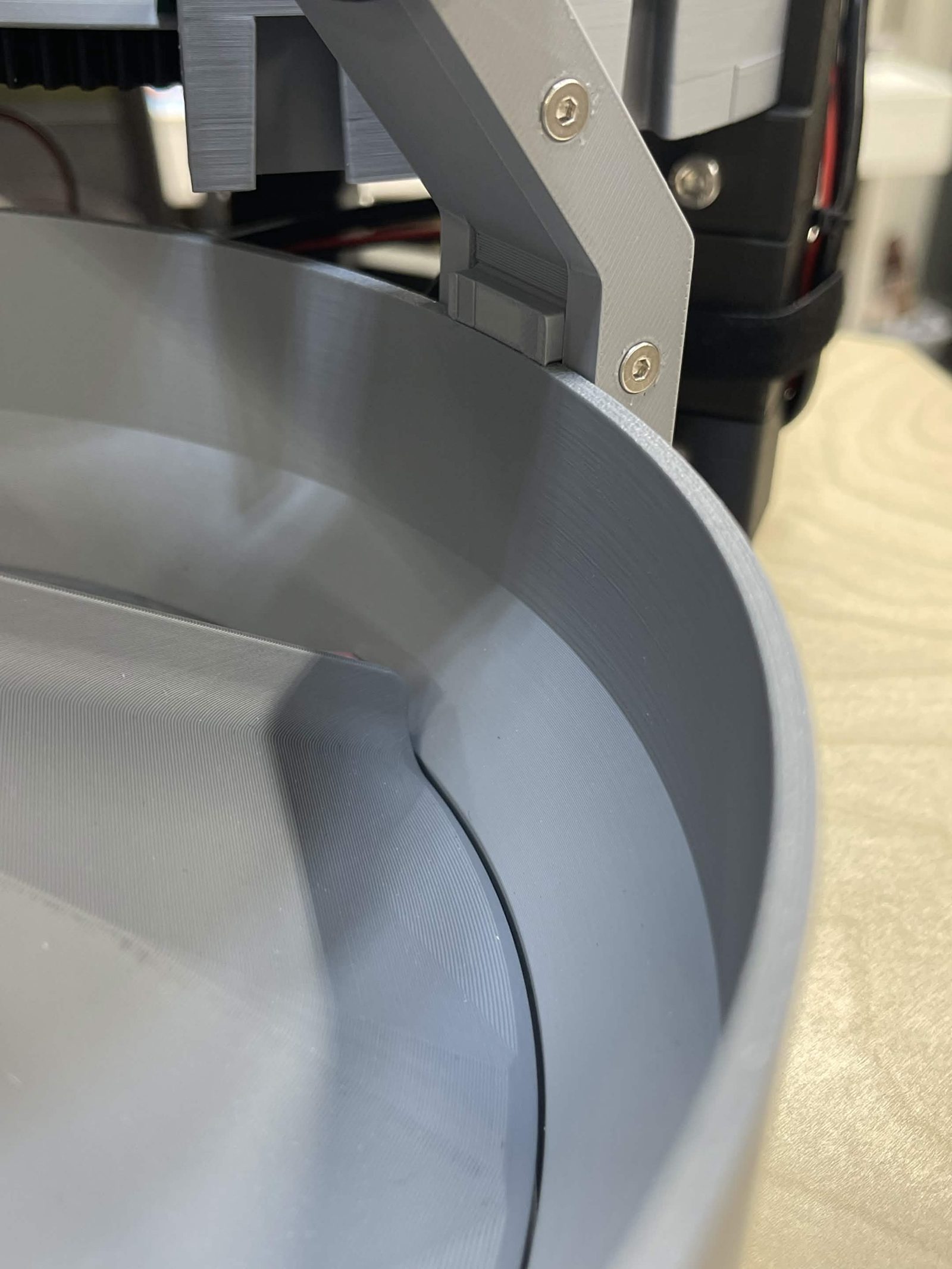
It goes on from underneath. Offer the arm mount up to the bottom edge of the channel wall, feed its rail into the dovetail, and push it up until it clips over the top edge. Nothing screws into this joint.
A camera has to see its channel's drop zone and its exit in the same frame. You check that at first setup step 7; if one cannot, its lamp is in the wrong dovetail.
The dovetail on the arm can break when a lamp needs to be removed and repositioned. Use caution if repositioning is needed.
Step 8 Turn it all by hand
Run parts through the whole cascade by hand, one channel at a time, before wiring the steppers. Anything that needs a nudge here will jam under power. Wiring is on the electronics page.
The finished result
Four channels standing at their own heights, each one dropping into the next.
Back to the feeder.