
Parts — Ordering the harness
Ordering the wire harness
ReferenceThe pack you send a cable vendor. Every drawing on the machine with its bill of materials, the spec they build to, and the zip.
This is the only page that carries the harness drawings. Everywhere else on the site links here, so a cable is drawn once and a redrawn harness updates in one place.
You do not have to order the harness. Every cable can be bought ready made or built on the bench. To build them yourself, use the Helpers pages and the bill of materials under each drawing, and skip to the drawings. Everything above the drawings is the specification for a vendor, and this page is for having the set made in one go.
↓ sorter-v2-harness-rfq.zip cover sheet + every drawing (PDF/PNG/SVG/HTML) + a BOM per drawing (TSV) + WireViz YAML sources
Global spec
What every cable is built to, whoever builds it.
- Wire
- UL1007 stranded, 300 V, tinned copper
- Gauges
- 18 AWG (0.82 mm²) (PSU box internals) · 22 AWG (0.33 mm²) (all barrel-plug 24 V runs, LED feeds, limit switch) · 24 AWG (0.20 mm²) (stepper cables, set by the JST-PH contact limit)
- Colours
- Red = +24 V, black = GND on every 2-conductor power cable. Stepper colours are on the drawings.
- Barrel jacks and plugs
- 5.5 mm (0.217 in) outside, 2.1 mm (0.083 in) inside, centre-positive, rated 5 A or better. Confirmed against the Waveshare hub (their part DC-044). 5.5 × 2.5 mm (0.217 × 0.098 in) exists, looks identical and does not mate, so put 2.1 on every line of the order.
- Length tolerance
- ±10 mm (±0.4 in), and ±25 mm (±1 in) is fine on anything 920 mm (36 in) or longer
- Bare ends
- Strip 5 mm (0.2 in), tin
- Labelling
- Each cable labelled with its ID from the schedule below (
W2,S1…) on a wrap-around label near end A, which is the left-hand end in the schedule. S1 to S4 are labelled at both ends: four identical cables land within inches of each other at the board and at the motors, and they cannot be told apart once unplugged. Printed laser labels or printed heat shrink are both fine. - Acceptance test
- 100% continuity, every conductor, end to end. On
S1toS4that means checking the position map under Channel stepper lead, not just that each wire arrives. No hipot. No UL listing or IPC class is asked for at this stage. - Packaging
- One bag per cable type, ID on the bag
- Parts and brands
- The vendor sources the connectors to the spec in the connector table. Where a row gives a part number it is the one the machine was designed against, and any RoHS-compliant equivalent that mates and crimps the same is fine.
- Order quantity
- 2 full sets, because spares are cheap. Treat them as the sample run.
Cable schedule
Every cable and lead the harness is made of, one row each, with its ID. Cables that are bought ready made (the ribbons, the USB cables, the mains cord) are not part of the harness and are not listed. The IDs are the same on the drawings, on the wire harness page and on the labels, so a cable keeps one name everywhere. Socket references (J1, J27…) are the sockets on basically board v1.3, and a socket on a layer board is named as such. End A is the end that gets the label.
| ID | Qty | End A | End B | Length | Wire |
|---|---|---|---|---|---|
| PJ1, PJ2, PJ3 | 3 | Panel-mount DC jack, female, on the PSU box plate | Two insulated M3.5 fork terminals, onto the PSU's paired screws (7+4, 8+5, 9+6) | 100 mm (4 in) | 18 AWG (0.82 mm²), red and black |
| W1 | 1 | DC plug, male, into PJ1 | JST VHR-2 housing into board J1, pin 1 = +24 V, pin 2 = GND | 920 mm (36 in) | 18 AWG (0.82 mm²), red and black |
| W2 | 1 | DC plug, male, into PJ2 | Bare, tinned, into the USB hub's 2-pin 24 V terminal | 310 mm (12 in) | 22 AWG (0.33 mm²), red and black |
| W3 | 1 | DC plug, male, into PJ3 | Bare, tinned, spliced to the buck converter's input leads | 150 mm (6 in) | 22 AWG (0.33 mm²), red and black |
| L1, L2, L3 | 3 | 2-position Dupont housing, 2.54 mm (0.1 in), into board J8, J9, J10: black wire in the cavity at the moulded arrow, red in the other | Inline DC socket, female | 920 mm (36 in) | 22 AWG (0.33 mm²), red and black |
| L1p, L2p, L3p | 3 | DC plug, male, into the matching L1 to L3 socket | Bare, tinned, to the clamp-on connector on the LED strip | 150 mm (6 in) | 22 AWG (0.33 mm²), red and black |
| LIM | 1 | 3-position Dupont housing into board J5: position 1 (the cavity at the moulded arrow) ground, position 2 signal, position 3 empty. Black for ground, white for signal | Two insulated #187 quick-connect receptacles, onto the limit switch | 610 mm (24 in) | 22 AWG (0.33 mm²), black and white |
| S1, S2, S3, S4 | 4 | JST PHR-4 into board J27, J31, J35, J39 | JST PHR-6 into the motor's own socket, positions 1·4·3·6 (see the pin map) | 1 m (39 in) | 24 AWG (0.20 mm²), blue, green, red, black |
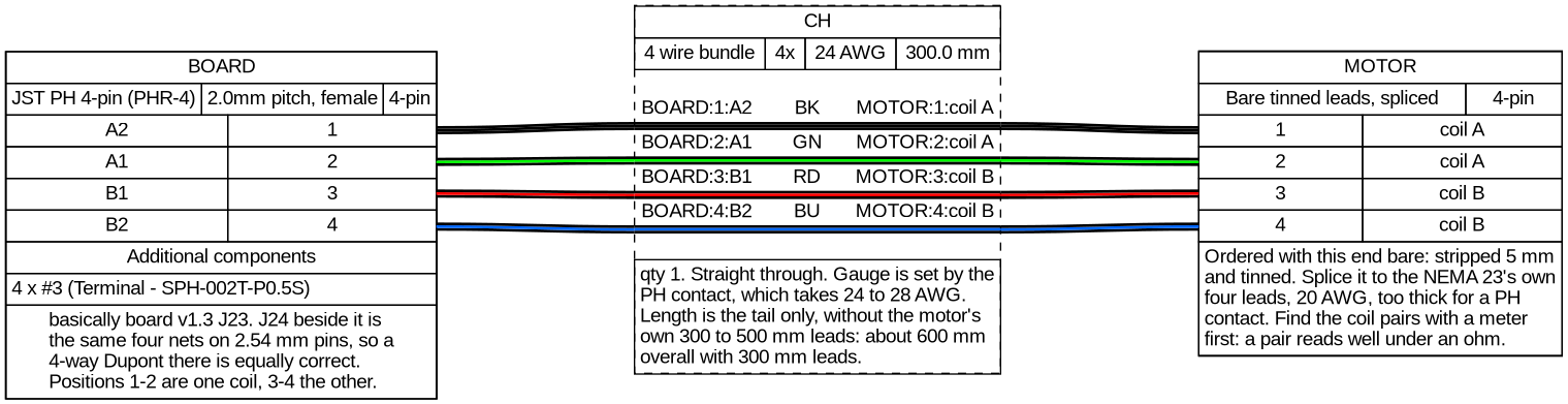
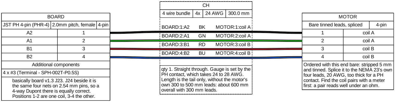
| CH | 1 | JST PHR-4 into board J23 | Bare, tinned, spliced to the chute motor's flying leads | 300 mm (12 in) tail, about 600 mm (24 in) overall with the motor's own leads | 24 AWG (0.20 mm²) |
CH is listed as the tail wire to cut, 300 mm (12 in); the motor's own leads are 300 to 500 mm (12 to 20 in) depending on the batch and are not part of it.
On L1 to L3, the optional inline socket and the plug on L1p to L3p can be left out, in which case the feed runs straight to the strip and the pigtail is not needed. The plug and socket are recommended because they let the lamp be unplugged close to where it is.
Connectors and terminals
What goes on the ends in the schedule. The part numbers are the ones the machine was designed against; where there is none, the spec is what to order to.
| Where | Housing or part | Contact or crimp | Used on |
|---|---|---|---|
| Board 24 V input | JST VHR-2N, 2-position | JST SVH-21T-P1.1 | W1 |
| Stepper, board end | JST PHR-4, 4-position | JST SPH-002T-P0.5S | S1 to S4, CH |
| Stepper, motor end | JST PHR-6, 6-position, 4 populated | JST SPH-002T-P0.5S | S1 to S4 |
| LED feeds, limit switch | Dupont housing, female, 2.54 mm (0.1 in): 2-position, and 3-position with 2 populated | Dupont female crimp contact, 2.54 mm (0.1 in). | L1 to L3, LIM |
| Limit switch | Fully insulated female quick-connect receptacle, #187 (4.75 × 0.5 mm, 0.187 × 0.020 in, tab), for 22 AWG (0.33 mm²). | Mates the Omron V-155-1C25 | LIM |
| DC plug | Barrel plug, male, 5.5 × 2.1 mm (0.217 × 0.083 in), centre-positive, 5 A or better. | Soldered or crimped per the vendor's process | W1 to W3, L1p to L3p |
| DC socket | Barrel socket, female, 5.5 × 2.1 mm (0.217 × 0.083 in), panel-mount on PJ1 to PJ3, inline on L1 to L3. | As above | PJ1 to PJ3, L1 to L3 |
| PSU terminal block | Insulated fork terminal, M3.5 stud, 8 mm (0.31 in) wide at most, for 18 AWG (0.82 mm²). | Crimp | PJ1 to PJ3 |
| Bare ends | Strip 5 mm (0.2 in), tin | No connector | W2, W3, L1p to L3p |
Dupont housings: the moulded arrow always marks the ground wire. The black wire goes in the cavity next to the arrow, and positions count away from the arrow. The housing has no key and the board's J8 to J11 have no reverse-polarity protection, so fit the lead with the arrow end over the pin the board prints GND (the round pad on J8 to J11; on J5 the pin on the square pad, with the empty position over 3.3V). Black is always ground and red is always +24 V. The self-builder pages (LED strip lead, limit switch lead) say the same.
Rows without a part number are specified by type and size, and the vendor sources them. The parts catalog carries each one with its per-machine count.
Ends the vendor cannot terminate
Some parts come with their own fixed leads or solder pads, so the harness cannot fully land on them. Those cables are ordered with one end bare and tinned, and joined on the machine.
- 24 V to 5 V USB-C buck (
W3): the converter has fixed input leads, so splice. - Chute stepper (
CH): flying leads out of the motor, so splice. Make the chute stepper lead. - LED strips (
L1p,L2p,L3p): a solderless clamp-on connector bites onto the cut strip, so nothing is soldered. Pick the variant with IDC crimp points on both sides and it takes the pigtail wire too.
Splice spec: solder splice plus adhesive-lined heat shrink, one sleeve per conductor and one over both. No twist-and-tape, no inline lever nuts.
The connectors themselves, with a photo and a per-machine count for each, are in the parts catalog under Wire harness.
The drawings
One per buildable cable, each with the bill of materials for it.
- 24V power distribution (PJ1 to PJ3, W1 to W3)
- Stepper cables (S1 to S4, CH)
- LED drops and limit switch (L1 to L3, L1p to L3p, LIM)
24V power distribution (PJ1 to PJ3, W1 to W3)
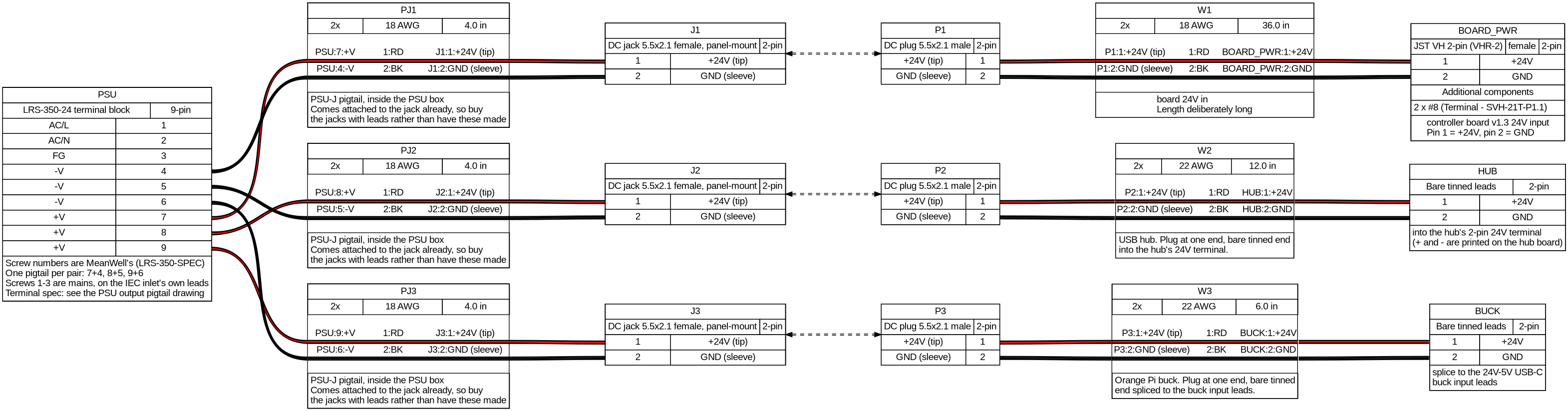
Download: PDF · PNG · SVG · HTML (drawing + BOM) · BOM (TSV) · YAML source
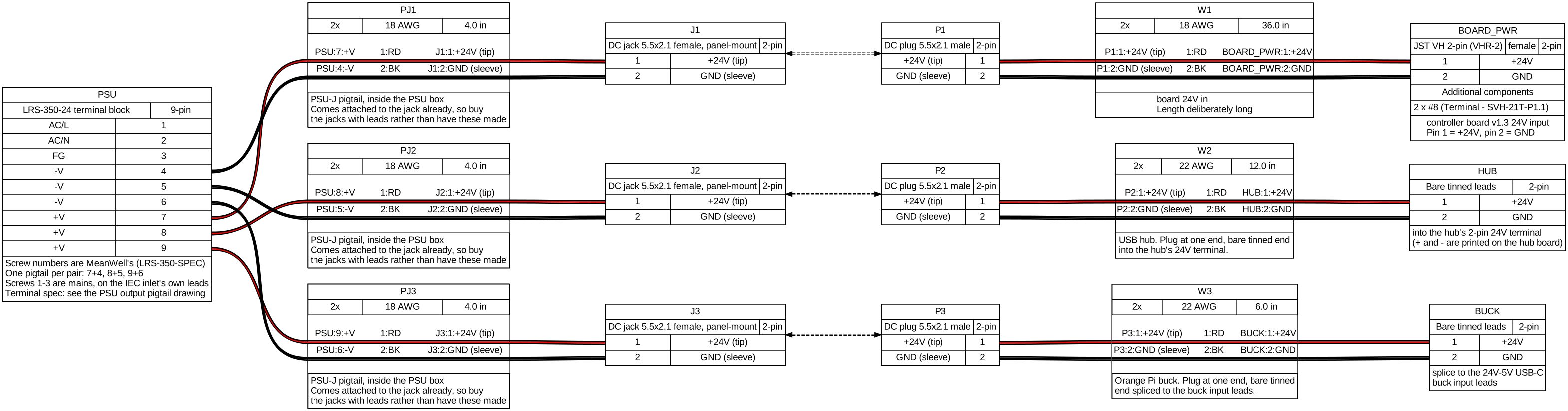
Loading the bill of materials for 24V power distribution (PJ1 to PJ3, W1 to W3)
PSU output pigtail (PJ1 to PJ3)
A sub-harness of 24V power distribution (PJ1 to PJ3, W1 to W3).


Download: PDF · PNG · SVG · HTML (drawing + BOM) · BOM (TSV) · YAML source

Loading the bill of materials for PSU output pigtail (PJ1 to PJ3)
24V to basically board v1.3 (W1)
A sub-harness of 24V power distribution (PJ1 to PJ3, W1 to W3).

Download: PDF · PNG · SVG · HTML (drawing + BOM) · BOM (TSV) · YAML source

Loading the bill of materials for 24V to basically board v1.3 (W1)
Stepper cables (S1 to S4, CH)
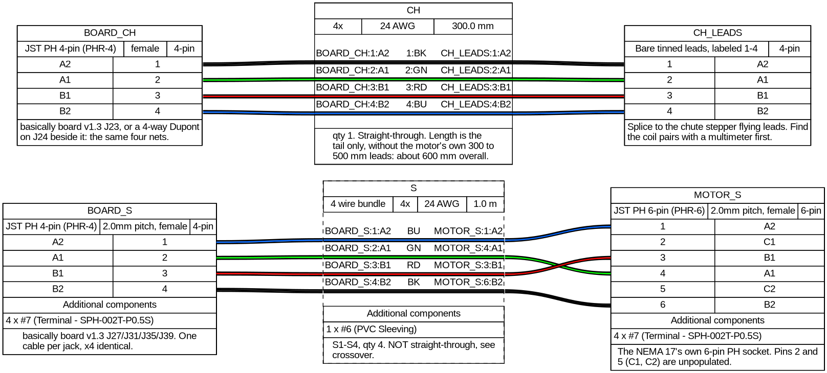
Download: PDF · PNG · SVG · HTML (drawing + BOM) · BOM (TSV) · YAML source
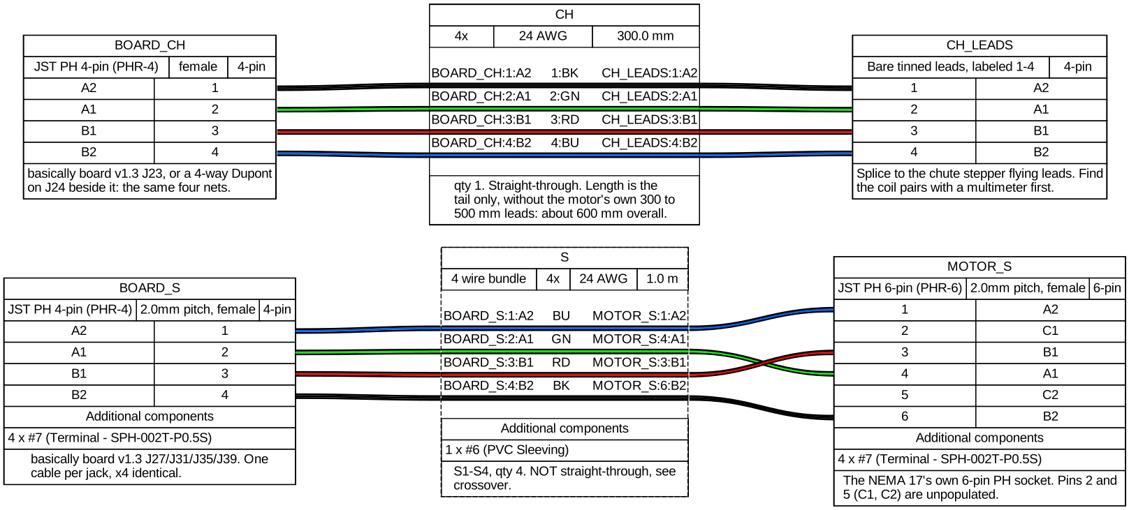
Loading the bill of materials for Stepper cables (S1 to S4, CH)
Channel stepper lead (S1 to S4)
A sub-harness of Stepper cables (S1 to S4, CH).
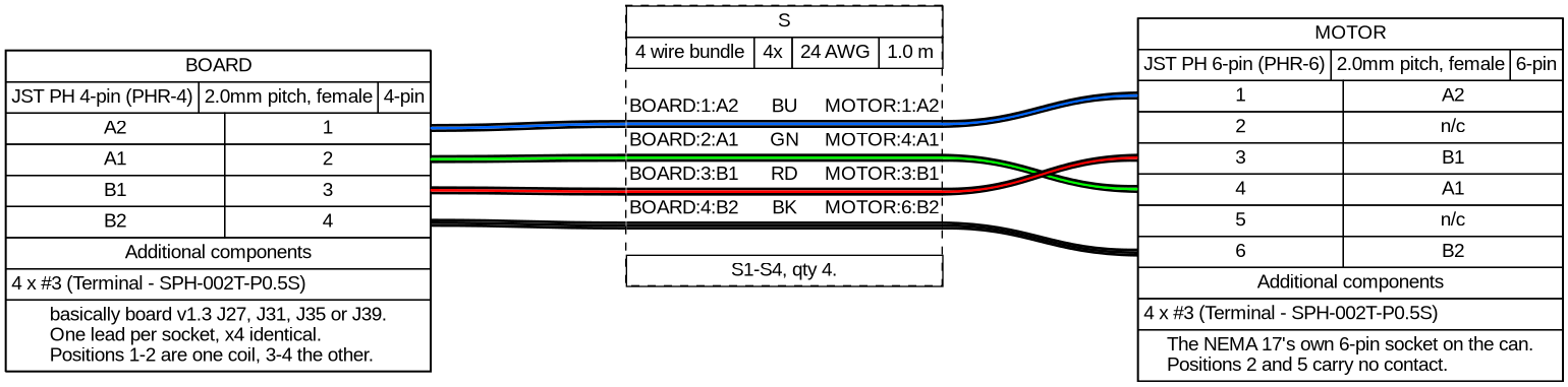
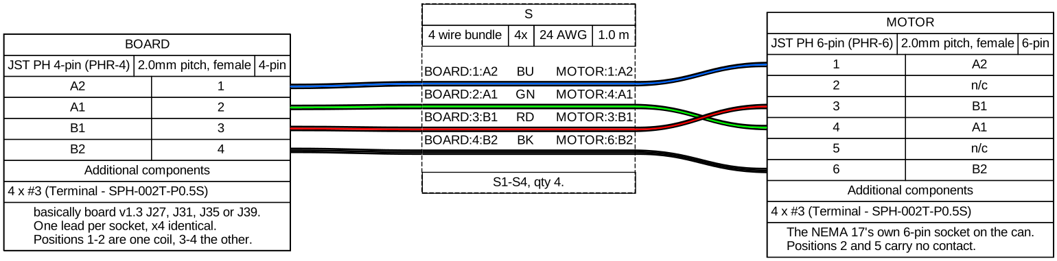
The four channel stepper cables (S1 to S4) are the only crossover in the harness, so this is the one to spell out. The motor end is a 6-position housing with four positions populated, so the four board positions land on motor positions 1, 4, 3 and 6. The nets match end to end; the positions do not.
| Board PHR-4 position | Net | Motor PHR-6 position | Colour |
|---|---|---|---|
| 1 | A2 | 1 | blue |
| 2 | A1 | 4 | green |
| 3 | B1 | 3 | red |
| 4 | B2 | 6 | black |
| — | — | 2 and 5 | unpopulated |
For the vendor, explicitly: this is not a straight-through cable, and the two ends have a different number of positions. Board 1 to motor 1, board 2 to motor 4, board 3 to motor 3, board 4 to motor 6. Motor positions 2 and 5 are left empty.
Motor end. The positions are the ones on the motor's own wire diagram in the StepperOnline 17HE15-1504S datasheet: position 1 is coil A+, 3 is B+, 4 is A-, 6 is B-, and 2 and 5 are empty. Coil A is positions 1 and 4, coil B is positions 3 and 6.
Download: PDF · PNG · SVG · HTML (drawing + BOM) · BOM (TSV) · YAML source
Loading the bill of materials for Channel stepper lead (S1 to S4)
Chute stepper lead (CH)
A sub-harness of Stepper cables (S1 to S4, CH).
Download: PDF · PNG · SVG · HTML (drawing + BOM) · BOM (TSV) · YAML source
Loading the bill of materials for Chute stepper lead (CH)
LED drops and limit switch (L1 to L3, L1p to L3p, LIM)
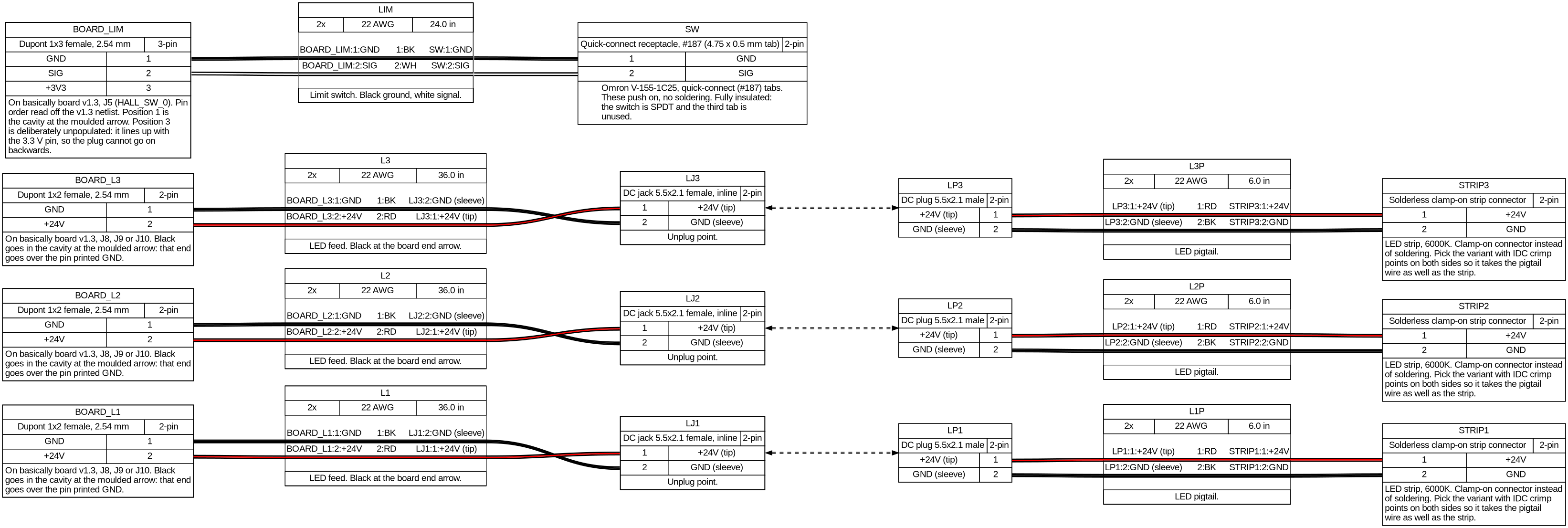
Download: PDF · PNG · SVG · HTML (drawing + BOM) · BOM (TSV) · YAML source
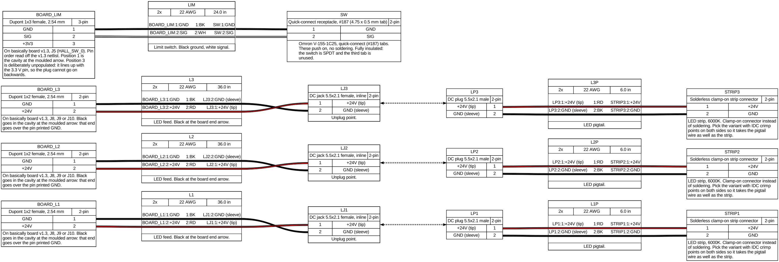
Loading the bill of materials for LED drops and limit switch (L1 to L3, L1p to L3p, LIM)
Chute limit switch lead (LIM)
A sub-harness of LED drops and limit switch (L1 to L3, L1p to L3p, LIM).
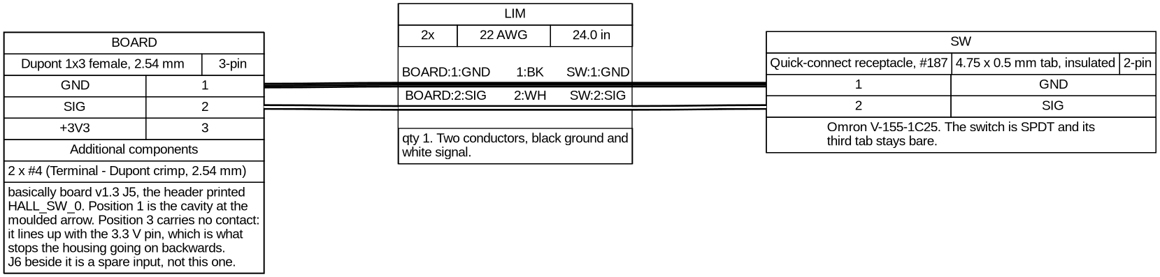
Download: PDF · PNG · SVG · HTML (drawing + BOM) · BOM (TSV) · YAML source
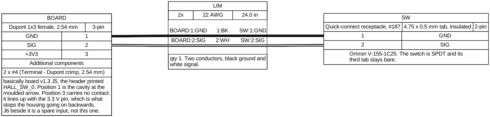
Loading the bill of materials for Chute limit switch lead (LIM)