
Bin frame — Build the hex frame
Build the hex frame
How-to guideThe hexagonal aluminum-and-bracket ring shared by every layer. Build one per planned layer, plus one for the top interface.
Parts needed
Aluminum extrusion (2020)
- 6× 320mm2020 aluminum extrusion, cut to 320 mm (piece A).
- 6× 158mm2020 aluminum extrusion, cut to 158 mm (piece B).
Printed parts
- 6×
- 6×
- 6×
- 12×
Screws
- 12× 16mm
A an interchangeable alternative works (hover for what).
Tools needed
- Hex key, 3 mm for a button head or 4 mm for a socket head
- Mallet or hammer with a cloth to protect the brackets
This guide builds one hexagonal frame: the outer ring of A extrusion and External bracket — side, with the six B spokes and Frame crossbeams held inside it by the Frame 90° brackets. No fasteners are used from step 2 onward.
An N-layer machine needs N + 1 of these: one per planned layer, plus one for the top interface. The bottom interface does not get a frame of its own — it hangs underneath the bottom layer's frame, off the same six spokes.
Pieces A and B are 2020 aluminum extrusion, cut to length. Each frame uses 6 A (320mm) and 6 B (158mm); the framing cut list has the exact dimensions.
This frame's fastener total is fixed: 12 M5x16 screws, one per extrusion end and so two per bracket, all driven in step 1. Steps 2 through 8 use none, and the frame needs no T-nuts of its own. The bin retainers that later bolt to this ring do use T-nuts, but with the roll-in T-nuts this machine specifies those go into the slot on the Bin retainers page, at the step that uses them.
Fastener icons match the parts list: the silhouette is the head shape, the colour is the thread size. M3 M4 M5 M6
Step 1 Assemble the outer ring
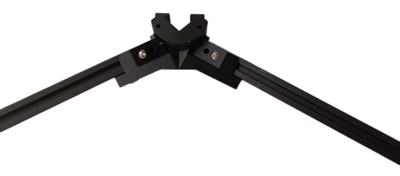
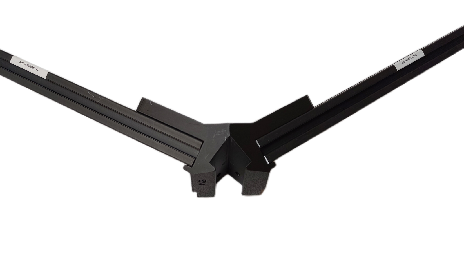
Slide piece A (Hex outer horizontal, 320mm) of aluminum extrusion into an External bracket — side. Where the extrusion goes in, the bracket has two holes next to each other, and you use one of them.
Standard: use an M5 × 16 mm socket / button head screw to tap directly through the outer of the two adjacent holes on the External bracket — side (the smaller of the pair), bracing it against the extrusion.
Option: if you would rather not tap and brace, place T-nuts in the extrusion and use the inner holes (the larger of the pair) to fasten into them instead. That is 12 more M5 T-nuts per frame, on top of the parts list above.
Taking the T-nut option? Use M5 × 12 mm socket / button head screws for it, not the 16 mm ones. That is 12 M5 × 12 mm socket / button head screws per frame in place of the 12 M5 × 16, and like the T-nuts they are not in the parts list above.
The bracket carries other holes that neither method uses, including one on its inward-facing side further along the extrusion. Leave those empty.
If you are using slide-in T-nuts rather than the roll-in ones this machine specifies, insert 4 into the outermost section of the extrusion before connecting the next External bracket — side, as this is the last time the ends of the extrusion are accessible. Those 4 are for the bin retainers, and Fitting T-nuts lists every other place the same applies. With roll-in T-nuts there is nothing to do here.
Repeat these steps to make two semi-circles: each is three sections of A extrusion (320mm) joined by three External bracket — side pieces. Slot the two half-hexagons together into a full hexagon and secure the join with 2 more M5 × 16 mm socket / button head screws. Build it this way rather than working your way around the hexagon.
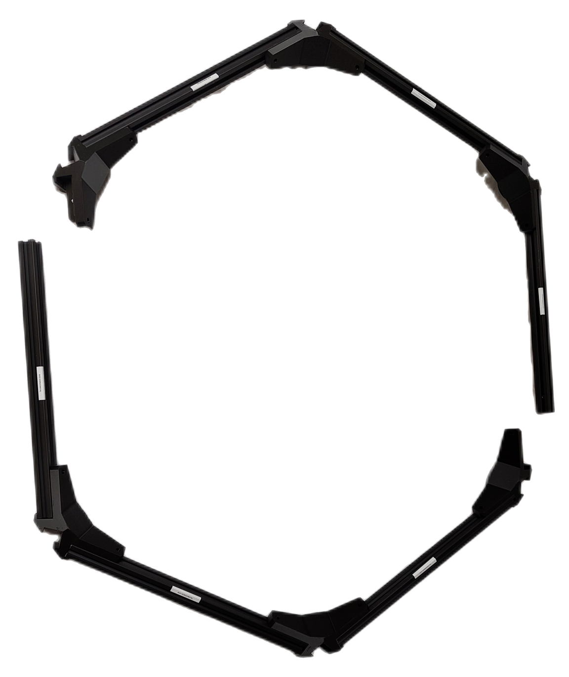
Set the ring aside; it goes on last, in step 5.
Step 2 Slide a spoke and crossbeam together
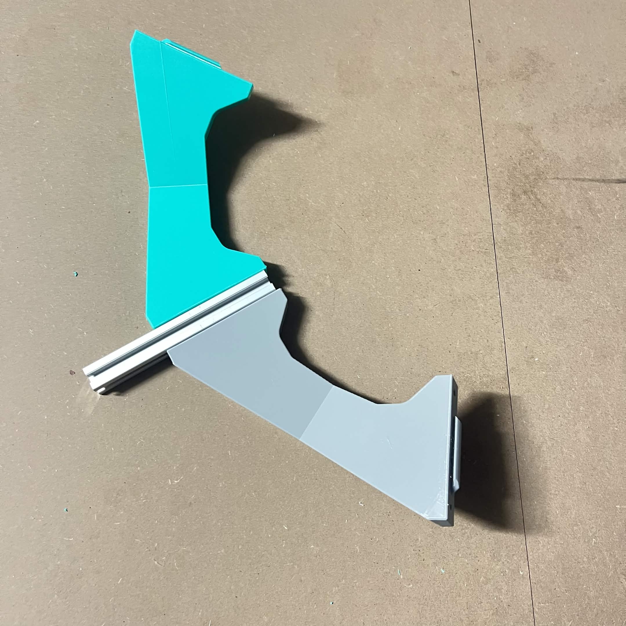
This part of the build has no hardware at all — every joint from here is a slide-in fit. It's a little fiddly, and a second pair of hands helps, but it's doable solo. Until the whole hexagon of spokes is closed the parts can feel loose and want to fall out with a small bump; once it's all together it's stable.
Slide a B spoke (158mm) and a Frame crossbeam together. For easy assembly, start with the crossbeam upside down.
Step 3 Continue around the hexagon
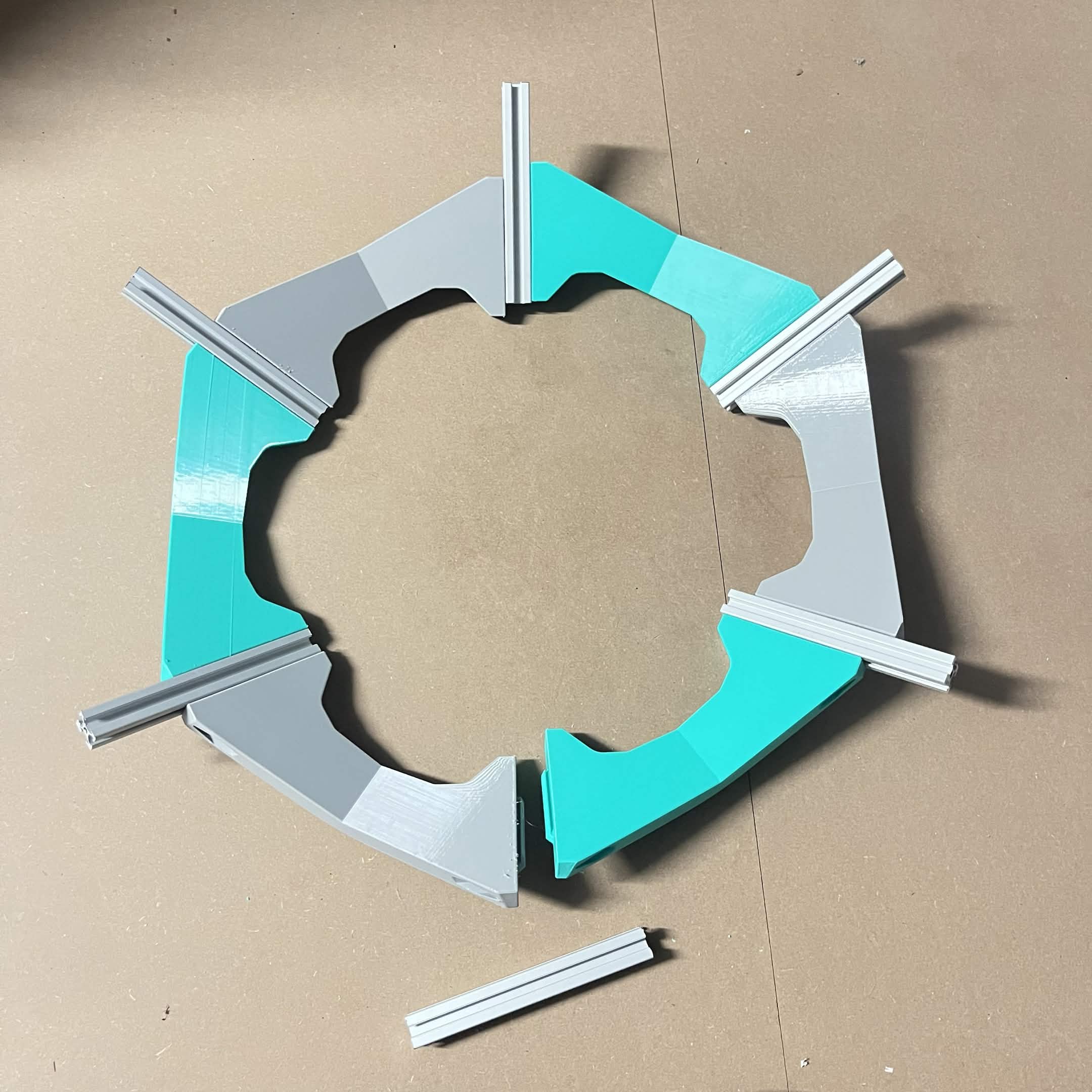
Repeat step 2 around the hexagon until you have used 6 Frame crossbeams and 5 B spokes (158mm). Deliberately hold the 6th spoke back — it closes the loop later, in step 7.
Step 4 Fit 10 of the 12 Frame 90° brackets
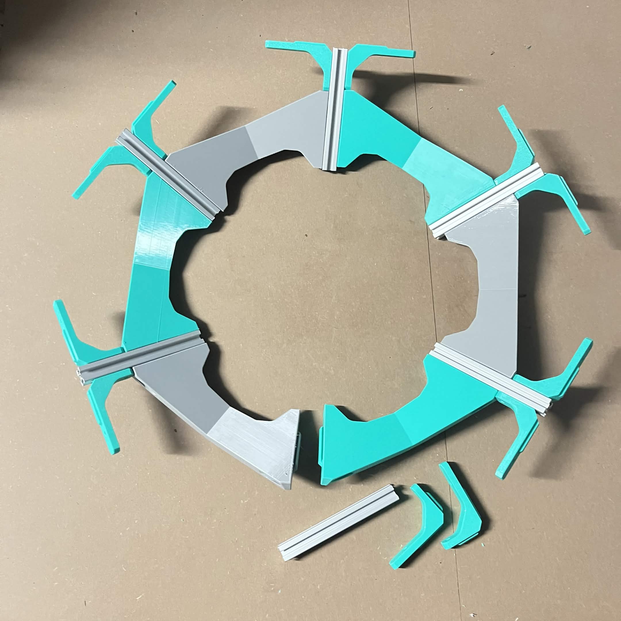
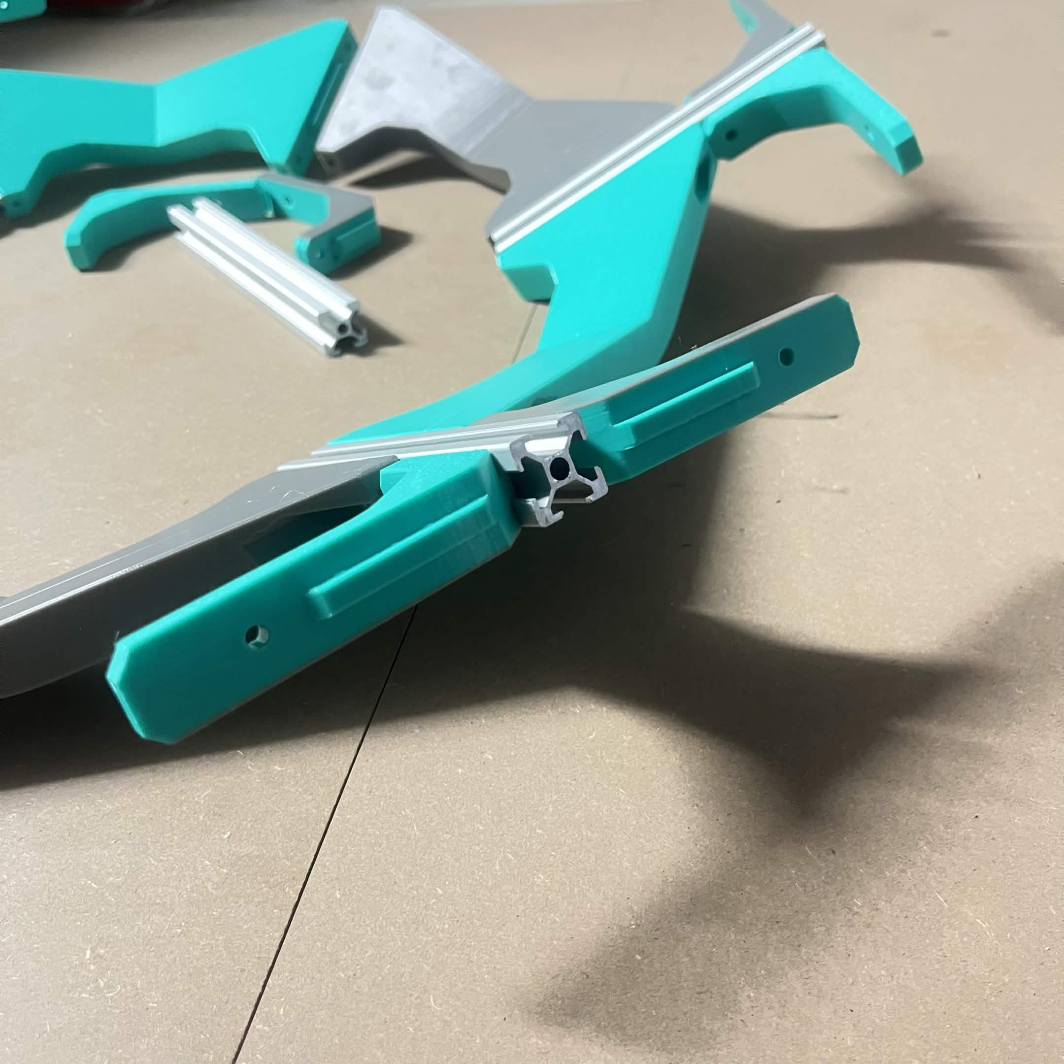
At each of the 5 closed spoke junctions, slide a pair of Frame 90° brackets on: the short leg onto the spoke, the long leg facing outward. Use 10 brackets for now — hold the last 2 back for the 6th junction, closed in step 7.
Step 5 Fit the outer ring
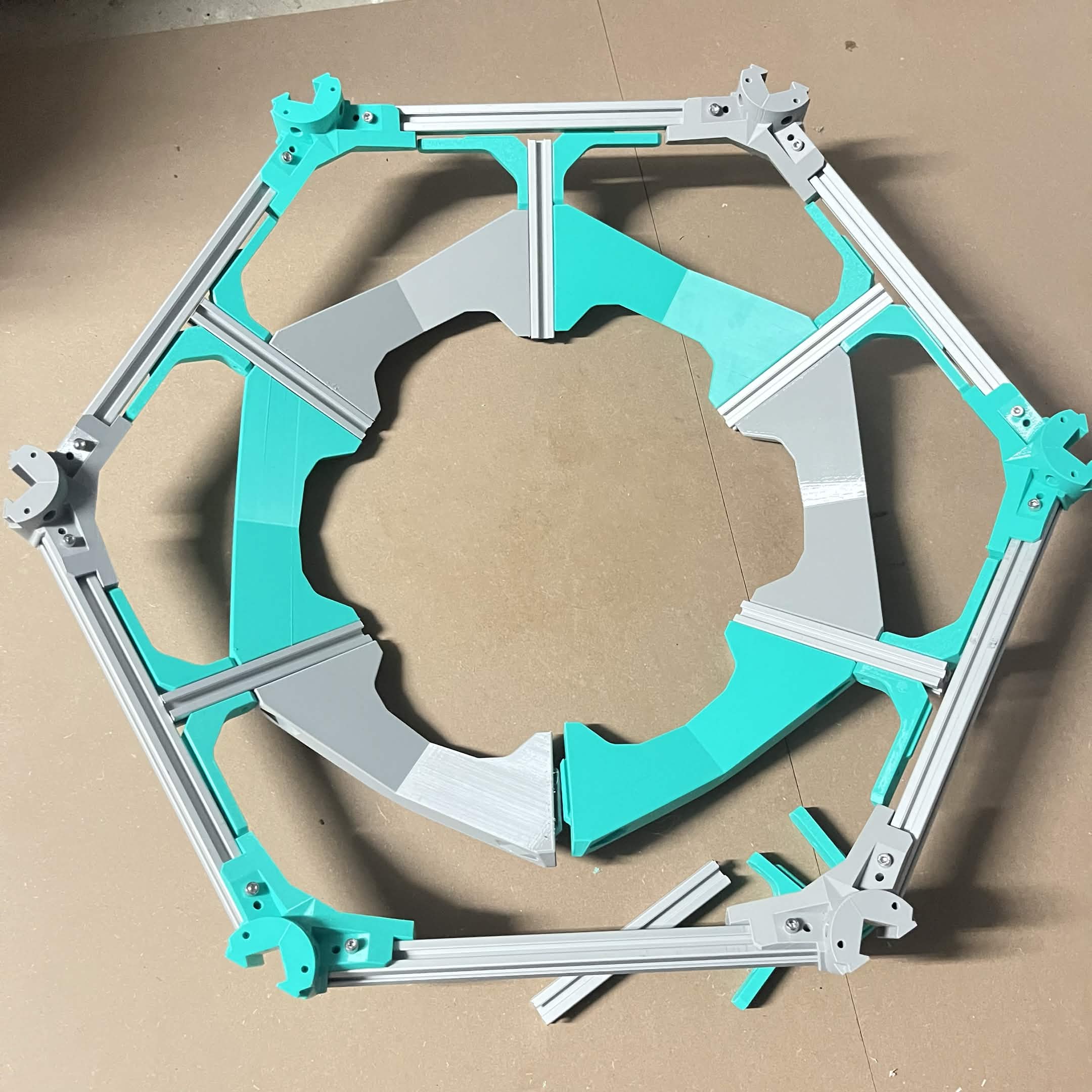
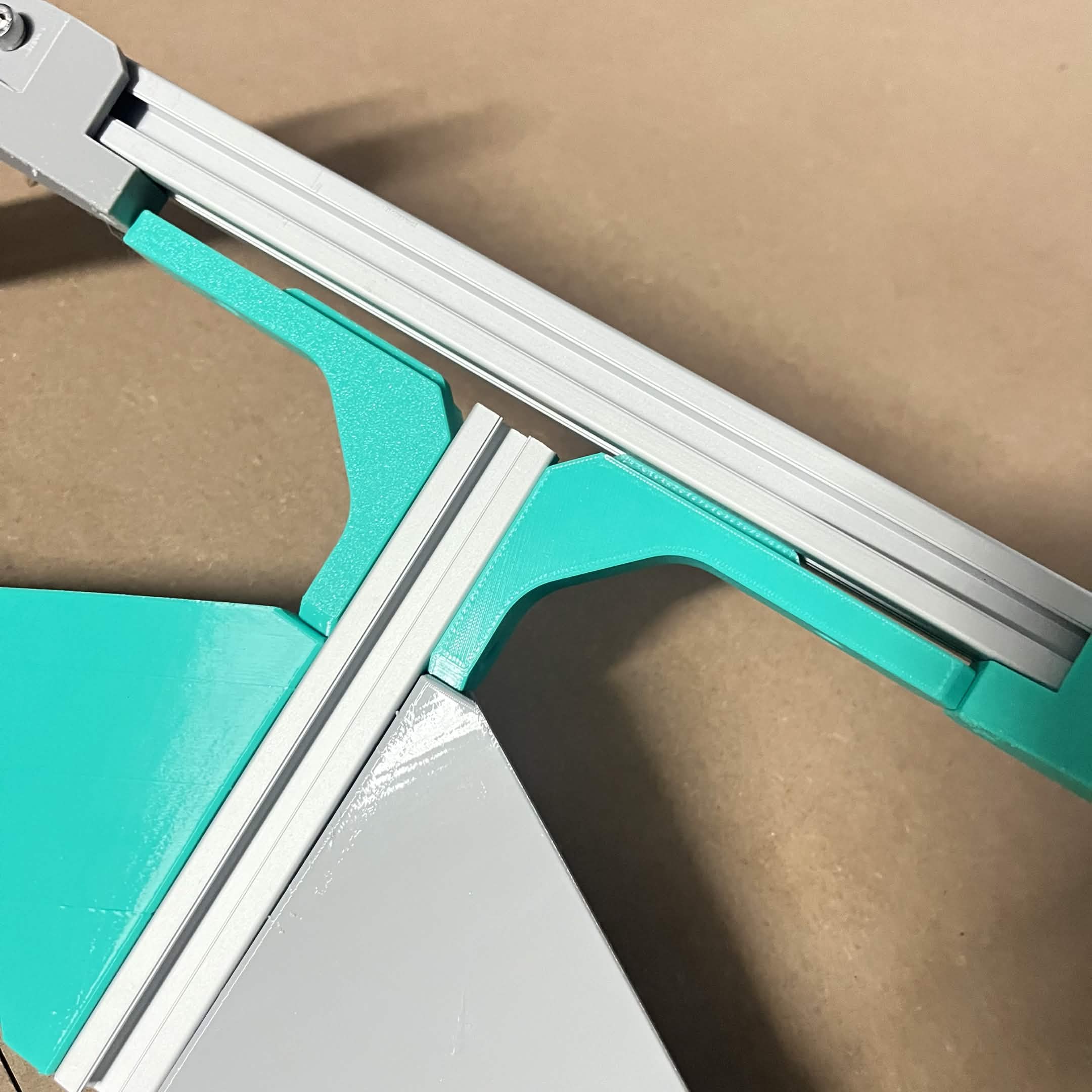
Grab the outer hexagon ring you set aside in step 1 and place it over the top of the spoke assembly. Wiggle it and apply outward pressure until all 10 long legs of the Frame 90° brackets are slotted into the T-slot channel of the A extrusion (320mm) — this is a slide fit, not a screw.
Step 6 Flip the frame
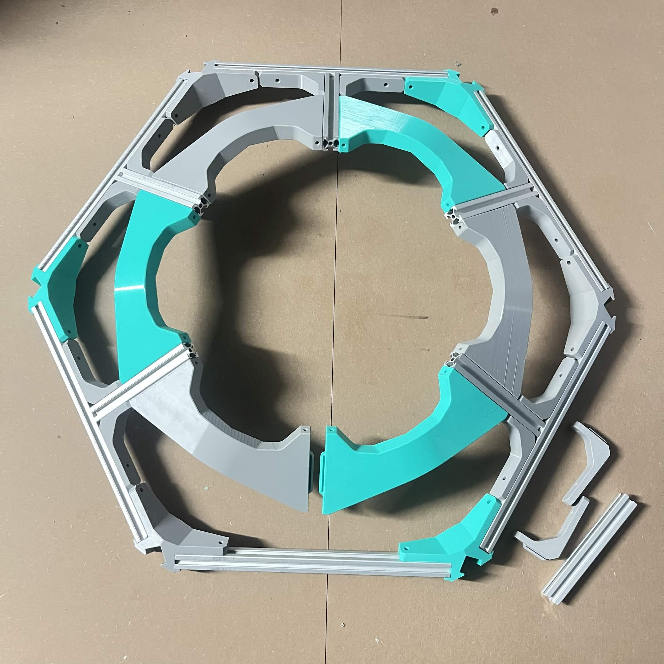
While holding the brackets in the ring, flip the whole assembly over — outward pressure on the brackets helps keep everything seated as you do. This is not just a change of viewing angle: the spoke assembly flips relative to the outer ring. Once flipped, the frame is the right way up for the finished build. (It's flipped again later, when it's actually attached to the machine — not relevant at this stage.)
Step 7 Close the ring
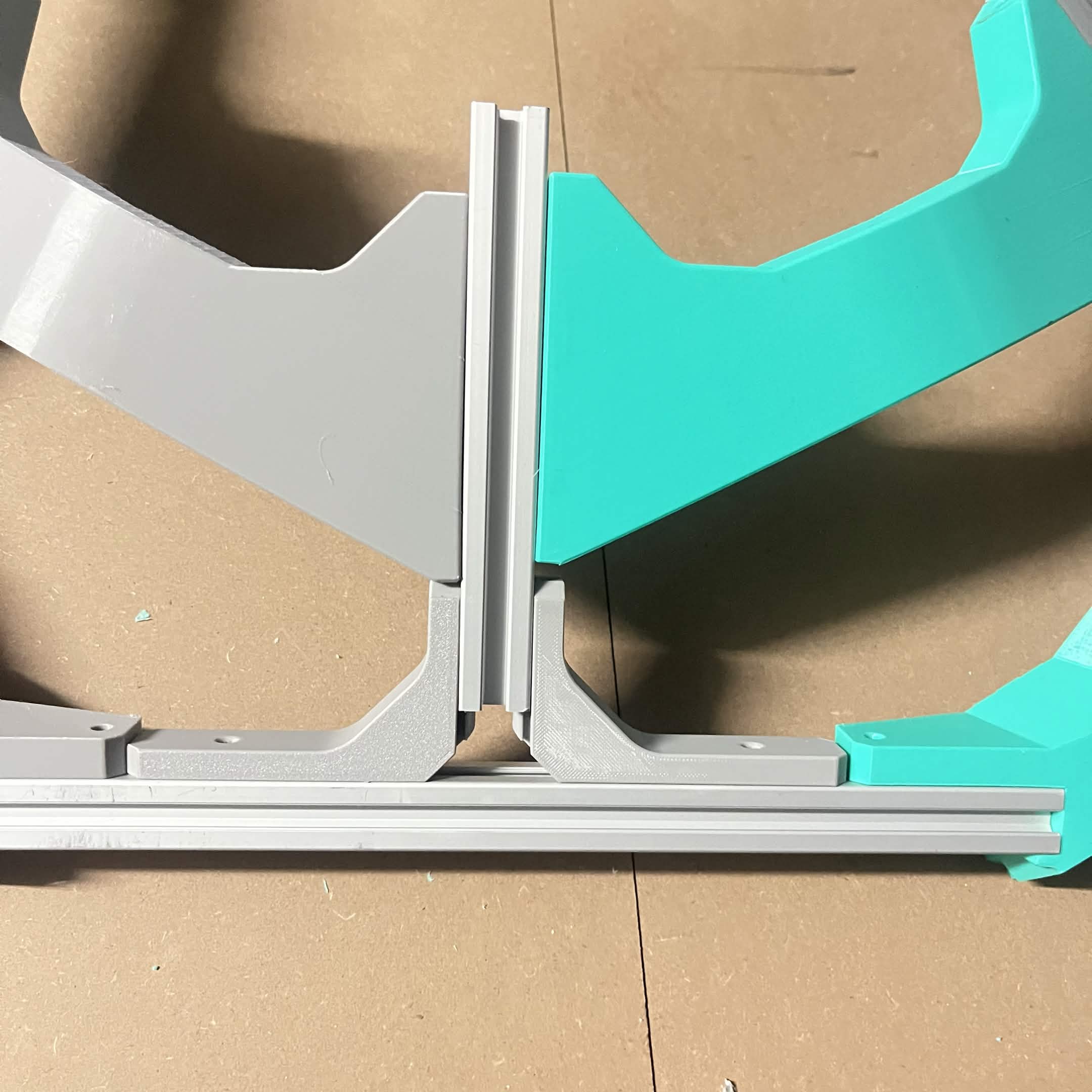
Slide the final B spoke (158mm) in from the top to close the ring, then fit the last 2 Frame 90° brackets at that junction.
Step 8 Check and snug every joint
Double-check that every Frame 90° bracket is still fully seated in its slot. A light hammer tap on each bracket, from the inside of the ring toward the outside, helps snug all the connections — use a mallet, or put a cloth between a hammer and the bracket, so you aren't striking the plastic directly.
Step 9 Fit the External bracket — covers
Building the bottom layer's frame? That one takes no External bracket — covers, so skip this step. Bottom layer fits it with External bracket — foot covers instead, one printed part in place of the cover and the External bracket — bottom vertical together. Every other frame takes all six, the top interface's included.
Push an External bracket — cover onto each of the six External bracket — sides. It takes no fasteners of its own, it is held by the fit; the side and the cover together form the collar that a layer's vertical extrusion later stands in.
This is the easy moment to do it. Once a vertical extrusion is standing in a collar, the cover is difficult to slide on past it.
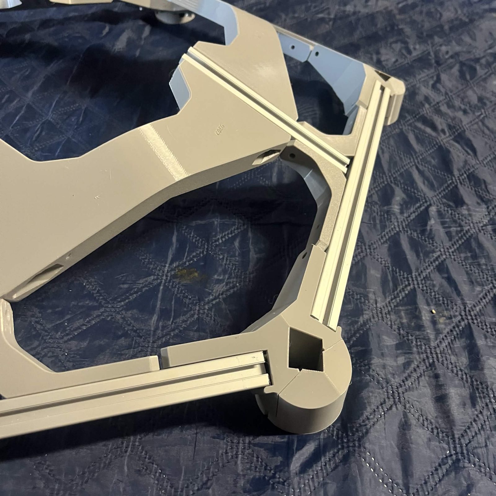
The finished result
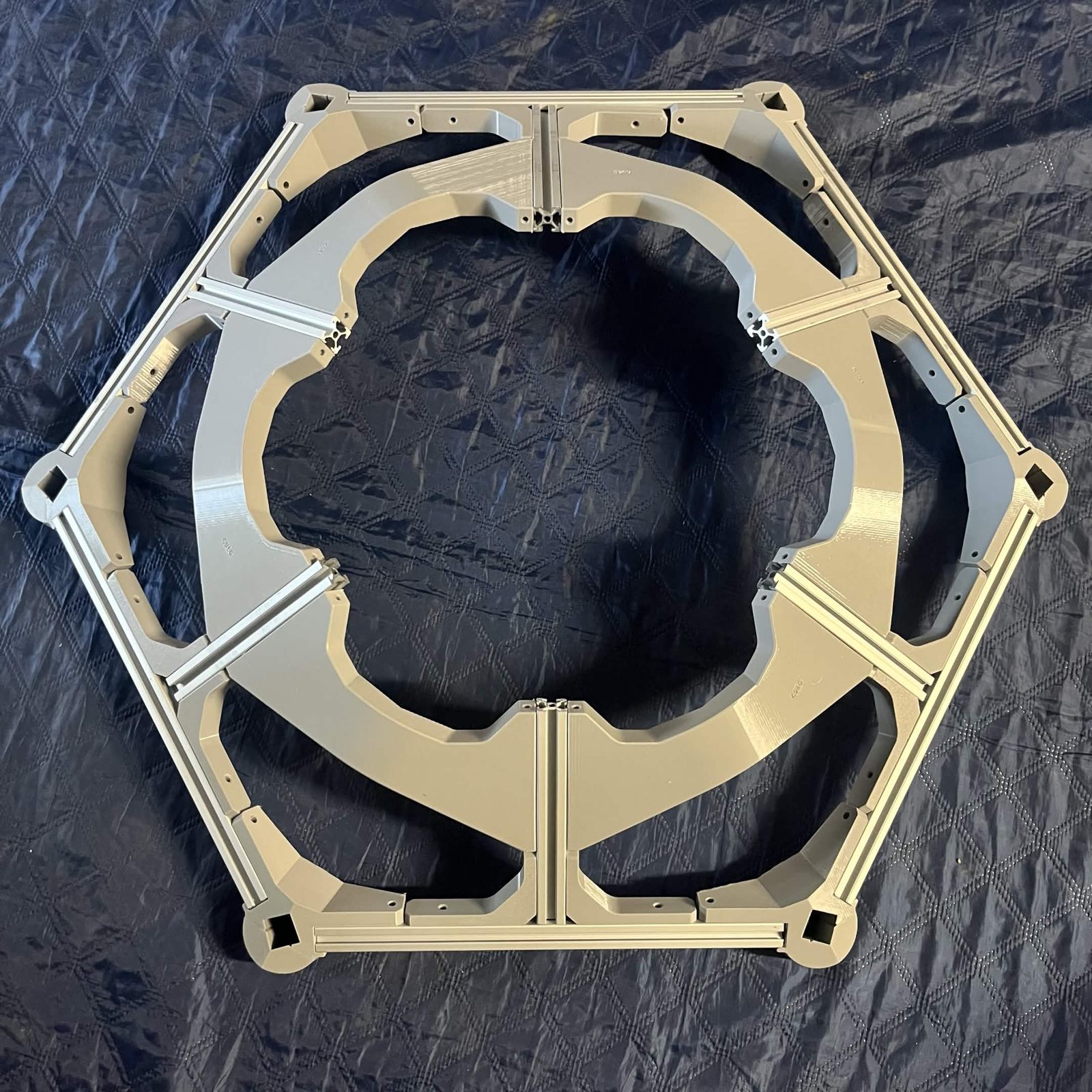
The Bin frame page contains the instructions for the entire stack, and is where you should return once you're done here.