
Electronics — Connecting the components
Connecting the components
How-to guideEvery cable between the PSU, the control board and the Orange Pi, and the socket each end goes into.
AI-generated first draft. Written from the basically board v1.3 board files and the cable schedule, not from an actual build. The sockets and the pinouts are read from the board itself and are real. The order of the steps is not checked against a machine. One step involves mains voltage: read the page fully before you start.
Parts needed
Computer
- 1×
- 1×
Wire harness
For the USB hub's 24 V lead (W2), one of these
Barrel plug on its own two wires, one of the three plugs, screwed into the hub's terminal
- 1×Three per machine, one each on W1, W2 and W3.
Lead with a barrel plug at each end, into the hub's DC jack (only if the housings are far apart)
- 1×Alternative to the plug in the hub's terminal, only when the housings are mounted too far apart for that plug's lead.
- 1×
- 1×Optional. About 10 m (33 ft) for the machine, over every lead you make.
Electronics
- 1× 1.2m
A an interchangeable alternative works (hover for what).
Tools needed
- Multimeter
- A small screwdriver, for the hub's power terminal
- Side cutters or wire strippers, only if the plug's two wires do not already have bare ends
- Only if you make your own control board 24 V lead (W1): wire strippers and a crimp tool
- Optional, for the sleeving: scissors and tape, or a hot knife
The PSU box, the control board housing and the Orange Pi housing are all bolted to the frame, and the cables are made or bought. This page plugs them together, and screws the USB hub's power wires into the hub. Nothing here needs a soldering iron.
Make these leads before you start. Each has a page that builds it, and the step named plugs it in.
Make the control board's 24 V lead (W1) before you start. One barrel plug at the PSU end and a JST-VH housing at the board end, 920 mm (36 in) of 18 AWG (0.82 mm²) pair between them. Step 1 plugs it in.
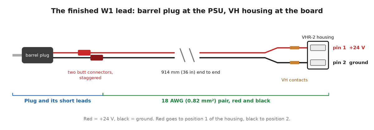
W1), with a moulded plug. Diagram: author not recorded.Make the Orange Pi's 24 V lead (W3) before you start. A barrel plug on the buck converter's own input wires, with the converter's USB-C lead going on to the Pi. Step 7 plugs it in.
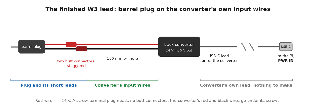
W3), with a moulded plug. Diagram: author not recorded.Make four channel stepper leads (S1 to S4) before you start. Each is the motor's own lead with its Dupont plug replaced by a 4-pin JST-PH housing. Step 2 plugs them into J27, J31, J35 and J39.
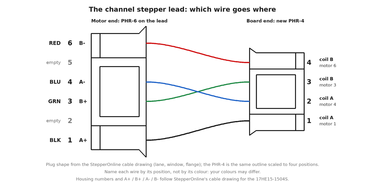
S1 to S4): the motor's 6-pin housing on the left, the 4-pin board housing on the right. Diagram: author not recorded.Make the chute stepper lead (CH) before you start. A 24 AWG (0.20 mm²) tail spliced onto the motor's four leads and ending in a 4-pin JST-PH housing. Step 2 plugs it into J23.
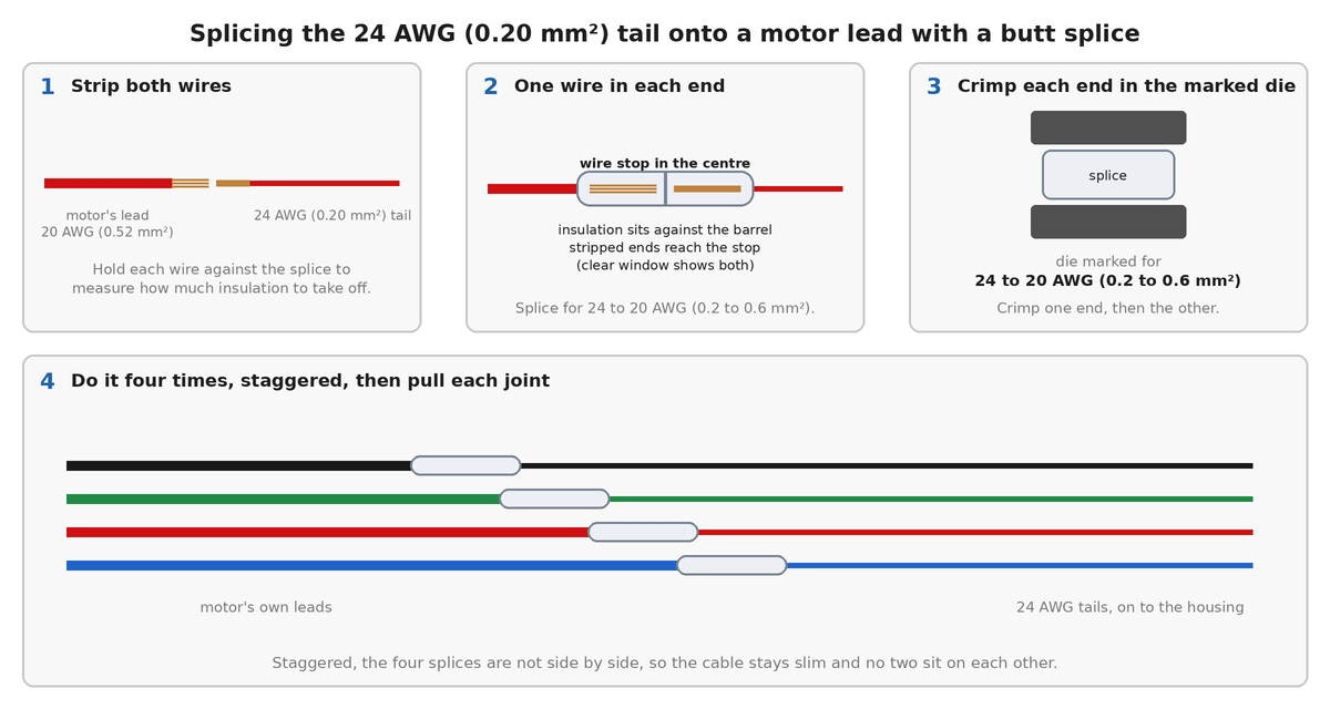
CH). Diagram: author not recorded.Make the chute limit switch lead (LIM) before you start. A 610 mm (24 in) pair with two #187 push-on receptacles at the switch end and a 3-pin Dupont housing at the board end. Step 3 plugs it into J5.
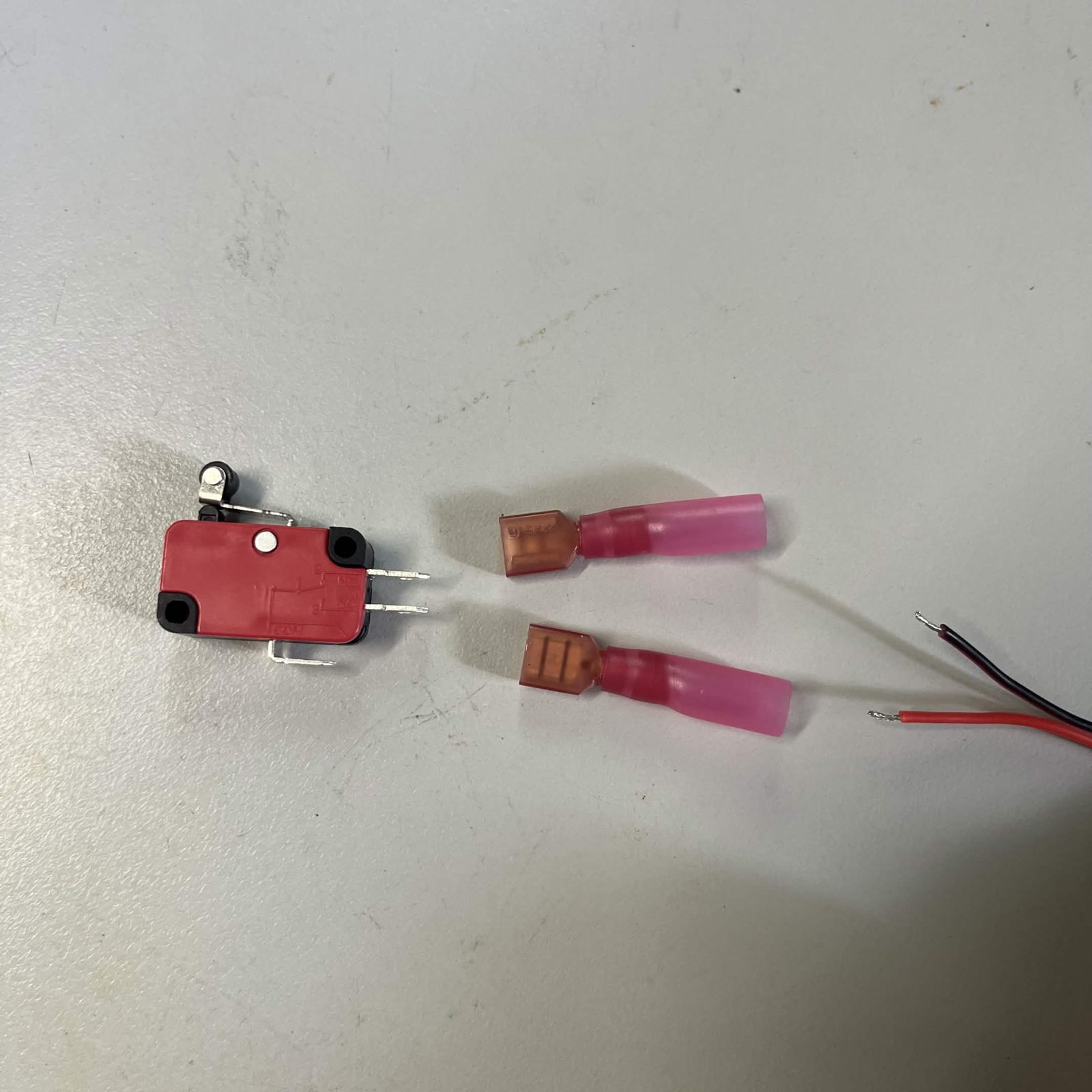
LIM): two #187 receptacles on the pair. Photo: BrickCycleAlice.Prepare three LED strips with their cables before you start. Each lamp has a strip with a short pigtail (L1p to L3p) ending in a barrel plug, and a board cable (L1 to L3) of about 920 mm (36 in) with the matching socket and a 2-pin Dupont housing. Step 4 plugs the board cables into the LED ports.
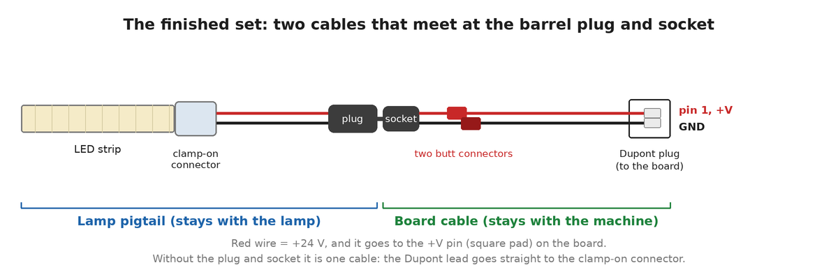
L1p) and the board cable (L1). Diagram: author not recorded.The PSU output pigtails (PJ1 to PJ3) are already in the PSU box. The USB hub's lead (W2) has no page: step 6 below connects it. Ordering the wire harness has the length and gauge of every lead.
Do not plug the mains lead (AC1) into the IEC inlet until the last step. The mains wiring inside the PSU box is finished and the box stays closed from here on, so nothing on this page goes near it, but the machine is not to see mains until every cable below is in and checked.
Every cable on this page
| Cable | From, and its connector | To, and its connector |
|---|---|---|
24 V, control board (W1) | PSU box jack, male DC barrel | Board J1, JST-VH 2-pin (make the control board's 24 V lead) |
24 V, USB hub (W2) | PSU box jack, male DC barrel | Hub 2-pin power terminal, bare wires (or the hub's DC jack, with a lead that has a barrel plug at each end) |
24 V, Orange Pi (W3) | PSU box jack, male DC barrel | Buck converter, then USB-C into PWR IN (make the Orange Pi's 24 V lead) |
Channel steppers (×4: S1 to S4) | Board J27 / J31 / J35 / J39, JST-PH 4-pin | The motor's own JST-PH 6-pin socket (make the channel stepper leads) |
Chute stepper (CH) | Board J23, 4-pin JST-PH (or J24 beside it, 4-pin Dupont on 2.54 mm (0.1 in) pins) | The motor's flying leads, spliced to a thinner tail and crimped into a PH housing (make the chute stepper lead) |
Chute limit switch (LIM) | Board J5, 3-pin Dupont, 2 positions used | Two #187 push-on tabs on the switch (make the limit switch lead) |
Camera lamps (×3: L1 to L3) | Board J8 / J9 / J10, 2-pin Dupont | Barrel socket, which takes the barrel plug on the lamp's pigtail (L1p to L3p) (optional but recommended; without it the cable runs to the strip) (prepare the LED strip) |
Ribbon to the layers (RIB1) | Board J17, 16-pin IDC | J3 on the first layer board, 16-pin IDC |
Pico to hub (U2) | Micro USB on the Pico | USB-A on the hub |
Hub to Orange Pi (U1) | USB-A on the hub | UP USB3.0 on the Pi |
| Cameras (×3) | The camera's own USB lead, one IMX415 and two OV9732 | USB-A on the hub |
Ordering the wire harness calls the first three W1, W2 and W3, the steppers S1 to S4 and CH, the limit switch LIM, the lamps L1 to L3, and the ribbon RIB1. The two bought USB cables between the Pico, the hub and the Orange Pi are U2 and U1; the cameras' own USB leads have no label.
The three 24 V leads (W1 to W3)
All three plug into the PSU box's three DC jacks, which are the same 24 V, so it does not matter which lead goes in which jack. Push each one fully home. Nothing else runs off the supply, the two cooling fans included, and there is no spare jack.
The buck converter is the only bought part of the three. The leads themselves are:
W1, control board- 18 AWG (0.82 mm²), 920 mm (36 in). Male DC barrel plug at the PSU end, JST-VH 2-pin (VHR-2) housing at the board end. No stock cable has that pair of ends, so a vendor makes it as part of the harness order, or you can make the control board's 24 V lead yourself.
W2, USB hub- 22 AWG (0.33 mm²), a moulded male DC barrel plug on its own short lead, with no second plug. Its two bare wires go into the hub, not into the board: step 6 shows how.
W3, Orange Pi- 22 AWG (0.33 mm²), 150 mm (6 in), a male DC barrel plug onto the buck converter's input wires. The buck's USB-C lead is the other half of the run.
The machine needs three male barrel plugs for these three, plus, if you fit the optional LED plug and socket, one on each of the three LED pigtails (L1p to L3p). Ordering the wire harness has a drawing of every cable in the machine, with the gauge, the length and both end connectors on it.
Every jack on the PSU box is 5.5 mm (0.217 in) x 2.1 mm (0.083 in), centre-positive. A 2.5 mm (0.098 in) plug looks the same and does not mate. Check the pin size before you buy a barrel lead.
Sleeving the leads you make (optional)
You can skip this and the machine works the same. The braided sleeving keeps the wires of each lead together as one tidy cable, protects them where they run along the frame past the moving parts, and is another way of securing the cables.
Where: over every lead you make yourself. Each helper page has the length and the step where it goes on:
- The four channel stepper leads (`S1` to `S4`), 1 m (39 in) each.
- The chute stepper lead (`CH`), about 1 m (39 in).
- The control board's 24 V lead (`W1`), about 920 mm (36 in).
- The limit switch lead (`LIM`), about 610 mm (24 in).
- The three LED board cables (`L1` to `L3`), about 920 mm (36 in) each, and their short lamp pigtails (`L1p` to `L3p`), 150 mm (6 in) each.
- The Orange Pi's 24 V lead (`W3`), about 150 mm (6 in).
The W2 lead to the USB hub, the USB cables (U1, U2) and the ribbon (RIB1) are bought parts with no page to make them, and the PSU box pigtails (PJ1 to PJ3) stay inside the box, so none of those is sleeved. In all, about 10 m (33 ft) for the machine: one 15.2 m (50 ft) roll.
When: while you make each lead, from the cut end, before you fit the connector that goes on it. A finished plug or housing may not go through the sleeving: the 6-pin housing on a channel stepper lead is too big for it, and a 4-pin PH housing is a tight fit that has not been tried. Do not plan on adding sleeving to a finished lead. The harness drawings sleeve the four channel stepper leads (S1 to S4) only; sleeving the rest is a choice, not part of the drawing.
How: the same on every lead.
- Push the braid together lengthwise to open it: it widens as it shortens. Feed all the wires of the lead into it together, so none of them is left outside.
- Cut it to length with a hot knife or a soldering iron with a blade tip, so the cut melts shut. Plain scissors leave the braid fraying. With no hot tool, wrap a turn of tape around the braid where you will cut, cut through the middle of the tape with scissors, and leave the tape on.
- Stop the sleeving 5 to 10 mm (0.2 to 0.4 in) short of each housing or plug, so the crimped contacts and the housings can flex and the sleeving never crowds into one.
- Hold each end with a small piece of heat shrink or a turn of tape, so that the braid cannot creep back along the wires.
Leave the sleeving loose enough to bend. A strap that anchors a lead goes on over the sleeving: pull it tight enough to hold, but not so tight that it crushes the braid.
Securing the cables
Fasten the leads to the frame with hook-and-loop (Velcro) straps rather than zip ties, wherever a lead may have to come undone. You will take the machine apart again, from the electronics layer up, and a zip tie has to be cut each time, which is slow when the bucket is loaded and the feeder is bolted down.
- This covers the motor leads too. Strap the four channel stepper leads (
S1toS4) and the chute stepper lead (CH) to the frame, and the same for the camera, LED, limit switch, USB and ribbon cables and the 24 V leads, anything that runs along the frame and may need to come loose. - Leave a little slack at every connector and splice, so that nothing pulls on the thin wire when a part moves or you lift a box.
- Do not make it neat yet. Run the machine for a good while first, and tidy once you know where the leads sit. The chute sweeps all the way round the machine, so check that no lead is in a spot where something that moves can catch on it.
The control board, socket by socket
Everything in steps 1 to 5 plugs into this board. It is drawn from above, the way you look at it once the housing is open.
The housing's openings reach the sockets along the edges of the board. If one of the sockets below will not reach with the cover on, take out the four countersunk screws, lift the cover, plug the cable in, and put the cover back. See Control board housing, step 6.
Step 1 Plug 24 V into the control board (W1)
The board's power input is J1, the big 2-pin socket in one corner of the board. It is the only connector of that size on the board, and the plug only goes in one way up. Pin 1 is +24 V and pin 2 is ground, and both are fused on the board. The board prints 24V beside pin 1 and GND beside pin 2: the red wire goes on the 24V side.
Step 2 Plug in the five stepper cables (S1 to S4, CH)
Each stepper has its own socket, and the socket decides which motor the software is driving. Plug them in as below.
| Socket | Printed beside it | The motor that goes on it | Cable end |
|---|---|---|---|
J23 | Stepper_A2 | Chute stepper | JST-PH 4-pin (CH), built on the motor's bare leads (a 4-pin Dupont housing goes on J24 beside it instead): make the chute stepper lead |
J27 | Stepper_A3 | C-channel 1 rotor | JST-PH 4-pin, one of S1 to S4 |
J31 | Stepper_A4 | C-channel 3 rotor | JST-PH 4-pin, one of S1 to S4 |
J35 | Stepper_A5 | Classification channel rotor (the software calls it the carousel) | JST-PH 4-pin, one of S1 to S4 |
J39 | Stepper_A6 | C-channel 2 rotor | JST-PH 4-pin, one of S1 to S4 |
On every stepper socket, pin 1 is the one on the square pad and carries A2; the PH sockets and the 2.54 mm (0.1 in) pins both put it at the same end. A PH housing is keyed and only plugs in one way round, so its position 1 is the end that goes over the square pad. A Dupont housing has no key, so go by the pad. The chute stepper lead (CH) page has the drawing.
Every socket has a row of 2.54 mm (0.1 in) pins beside it carrying the same signals, so a cable with a Dupont end goes on those instead: J24 beside J23, J28 beside J27, and so on, with each pin's coil name printed beside it so you can read them off the board rather than counting positions. Stepper_A6 is on the far side of the board on its own; the other four are in a row along one edge. Each socket is wired to the driver printed beside it, so that driver has to carry the address for that stepper. The addresses are set in preparing the control board, step 3.
Check the coils before you plug a motor in. A stepper has two coils, two wires each, and the plug has four holes: holes 1 and 2 feed one coil, 3 and 4 the other. Put a multimeter across the wires that should be a pair. A pair reads a few ohms; two wires from different coils read open circuit. If holes 2 and 3 are the pair, pull those two contacts out of the housing and swap them, or the motor will buzz and barely turn. Full pinout and the board-side footprint: the wire harness page.
Step 3 Wire the chute limit switch (LIM)
The switch tells the machine where the chute is. Its cable (LIM) ends in a 3-pin Dupont housing with only two positions filled, and it goes on J5, the header the board prints HALL_SW_0. The filled positions are ground and signal, and the empty one goes over the pin the board prints 3.3V. The housing is not keyed and fits either way round, so check that before you push it on: the limit switch lead shows it.
At the switch end, push the two #187 tabs onto the switch's COM and NC terminals. The switch has three tabs and one stays empty. Wired this way the circuit is closed while the lever is free and opens when the chute presses it, which is what the machine expects. If homing runs the wrong way round later, the setting is in the software, not the wiring.
Step 4 Plug in the three camera lamps
The board has four LED ports. The fan in the housing lid is already on one of them, so the three camera lamps take the other three. Each lamp comes with a prepared LED strip and a board cable (L1 to L3) of about 920 mm (36 in) of 22 AWG (0.33 mm²) with the Dupont housing on one end. The barrel plug on the strip's pigtail (L1p to L3p) and the matching socket on the cable's other end are optional but recommended: they make maintenance easier, because the lamp's power can be disconnected close to the lamp. Without them the cable runs straight to the strip.
| Port | Printed on the board | What goes on it |
|---|---|---|
J8 | LED_0_1 | Camera lamp |
J9 | LED_0_2 | Camera lamp |
J10 | LED_1_1 | Camera lamp |
J11 | LED_1_2 | The housing fan, fitted on the housing page |
The board prints +V beside the pin on the square pad of each port and GND beside the round one. The red wire goes to +V. The Dupont housing has no key and fits either way up, but the arrow moulded on it always marks the black (ground) wire on every lead here, so push it on with the arrow end over GND.
Four ports, two switches. J8 and J9 turn on and off together, and so do J10 and J11. So one lamp always comes on with the fan. Which lamp is on which output is picked in the software later, on the LED button for each channel.
The solder jumper beside each of these three ports should already be bridged, from preparing the control board, step 4. If you skipped it, do it before the lamps go on: the 180 Ω resistor in each port is there for a bare LED board and only dims a strip.
Plugging one in. Push the 2-pin 2.54 mm (0.1 in) Dupont housing on the board cable (L1 to L3) onto the port, red to +V, metering which pin that is first. If you fitted the plug and socket, push the lamp's barrel plug into the socket on the other end of that cable. Cable-tie the pair along whatever it runs down so it is not left hanging.
The barrel pair is optional but recommended, and it makes maintenance easier. It is the point where a lamp comes off, so the power to a lamp can be disconnected close to the lamp and the lamp unplugged without unwiring the board end. It is the same 5.5 mm (0.217 in) × 2.1 mm (0.083 in) size as a PSU output jack, so check what you are plugging into.
Then assign the output in software: Settings, the channel, the LED button, pick which output that lamp is on and set the brightness. Nothing lights until an output is assigned. The lamps' board cables are L1 to L3, and their pigtails L1p to L3p, in the cable schedule, which still draws every drop split at a barrel jack.
Step 5 Run the ribbon down to the layers (RIB1)
One flat 16-pin ribbon (RIB1), 1.2 to 1.5 m (47 to 59 in), runs from J17 on the control board down to J3 on the first layer board in the chute stack. Both ends are keyed, so it only goes in one way up.
The layer boards are already chained to each other with their own 300 mm (12 in) ribbons (RIB2), and their servos are already plugged in. Both happen as each layer adapter board is built and the chute tower goes together.
Step 6 Power the USB hub (W2)
The hub has its own 2-pin screw terminal for power, on its circuit board. The two wires of the plug's lead (W2) go in there. Do this with the PSU box not plugged in to the mains.
- Plug the barrel plug into a free 24 V jack on the PSU box. Push it fully home.
- Find out which of the plug's two wires is the + wire. Inside the plug's barrel there is a centre contact. The outer metal sleeve is the other contact. Touch one multimeter probe to the centre contact and the other to the end of each wire in turn, with the multimeter on continuity. The wire that beeps is +. Mark it, for example with a piece of tape.
- If the two wires do not already have bare ends, cut off a little of the plastic from the end of each so the bare copper is long enough to go all the way into the terminal.
- On the hub's circuit board, find the 2-pin terminal. The board prints
+and-next to it. Loosen both screws a few turns. - Push the + wire into the opening marked
+and the other wire into the opening marked-. Push each one in until no bare copper shows outside the terminal. - Tighten both screws, then give each wire a gentle pull. If a wire moves, tighten the screw more.
The plug's own lead (W2), about 310 mm (12 in) with the plug, is long enough when the Orange Pi housing, which carries the hub on its roof, is bolted next to the PSU box as in the frame drawing.
If you mounted the two housings further apart and the lead does not reach, buy a ready-made lead (`W2`) with a 5.5 mm (0.217 in) x 2.1 mm (0.083 in) barrel plug at each end, centre contact +24 V at both ends (it is listed in the parts above as the alternative). Plug one end into the PSU box and the other into the round DC socket on the hub. The terminal stays empty, so skip points 2 to 6 of the list above.
Step 7 Plug in the USB (U1, U2): the Pico, the hub and the Orange Pi
The Orange Pi talks to the control board over USB, through the powered hub. The three cameras are on the same hub.
- Plug the buck converter's USB-C lead into the socket the board prints
PWR IN. The Pi has two USB-C sockets that look the same and only the one markedPWR INis a power input. The other is USB 3.1 and DisplayPort, with no power function. Check that the converter is putting out 5 V before it goes anywhere near the Pi, as under Check the lead on Make the Orange Pi's 24 V lead (W3). - Run a USB cable (
U2) from the Pico's micro USB socket to any port on the hub. - Run a USB cable (
U1) from the hub to the port markedUP USB3.0on the Pi, the upper of the two stacked sockets. The hub comes with a USB-A to USB-A lead for this. - Plug the three cameras into the three remaining hub ports. Each one arrives with its own lead: the IMX415 4K module on the classification camera lamp, and the two OV9732 720p modules on the C2 and C3 feeder camera lamps.
That fills the hub: three cameras and the Pico, no spare port.
They have to be data cables. Many short USB cables carry power only and nothing will appear on the Pi. Use the powered hub as well: a hub running off the Pi's own power has been seen to brown the Pi out and crash it.
Step 8 Check it over, then plug it in
Before the machine sees mains:
- All three DC leads (
W1toW3) are in their jacks, and the PSU box is closed. - At the hub's power terminal, the wire from the plug's centre contact is under
+, and neither wire pulls out. - Every stepper plug is fully home, and no plug is hanging on one contact.
- The ribbon (
RIB1) goes from the board toJ3of the first layer board, and down the stack on the layer ribbons (RIB2),J4toJ3. - Nothing is resting on the fan blades.
Then plug in the mains lead (AC1) and switch the inlet switch on. The red power light on the Orange Pi comes on. The fan in the housing lid does not run yet, because the software switches it.
The finished result
Every cable between the three boxes in, and the machine switched on for the first time.
Next: software setup, which flashes the Orange Pi and the control board and then asks you which output each lamp and each stepper is on.