
Bin frame — Regular layers
Regular layers
How-to guideThe repeating bin layers above the base. Build N−1 for an N-layer machine.
Parts needed
Printed parts
- 6×
Aluminum extrusion (2020)
- 6× 154mm2020 aluminum extrusion, cut to 154 mm (piece C).
Screws
- 24× 16mm
A an interchangeable alternative works (hover for what).
Tools needed
- Hex key, 3 mm for a button head or 4 mm for a socket head
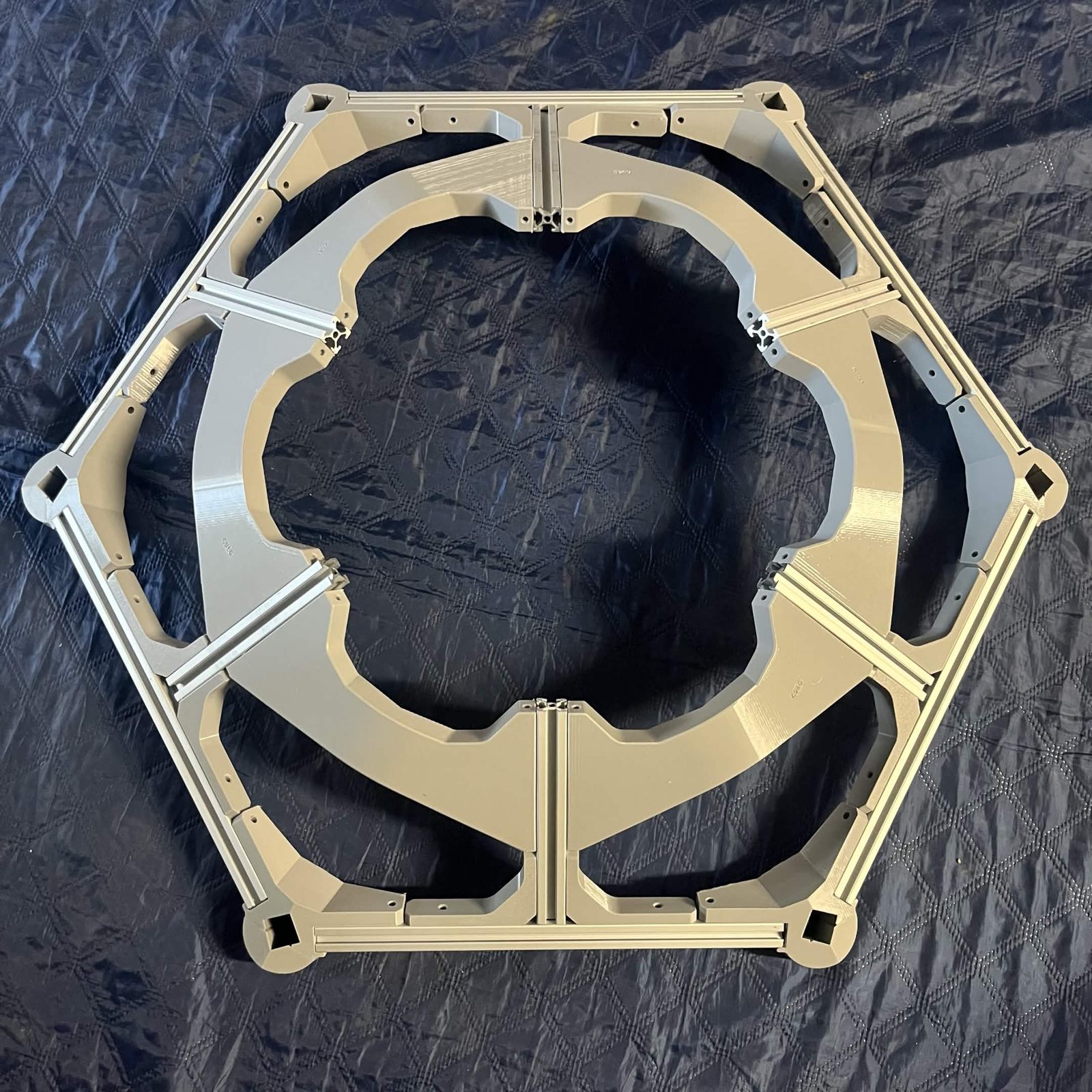
Each layer holds one chute-and-bin pair, built separately, that catches the pieces routed to it. A regular layer is the same hexagonal ring, vertical supports and flange joint as the layer below it.
This guide covers creating a regular layer, and every bin layer but the lowest one is a regular layer, so build N−1 of these for an N-layer machine. The bottom layer is the remaining one: it is this layer with foot extensions in place of piece C and the casters under them, and it has its own page.
Build a hex frame before you start. It's a required component of this page, not covered here.
Piece C is 2020 aluminum extrusion, cut to length. The framing cut list has the exact dimensions. Nothing on this page takes a T-nut .
The 24 M5 × 16 mm socket / button head in the list above are two pairs at each of the six corners, and nothing else on this page takes a screw:
- 12 clamping the External bracket — side onto piece C, 2 per corner (step 1)
- 12 through the External bracket — bottom vertical's outer holes onto the same extrusion, 2 per corner (step 1)
The hex frame's own 12 are on its page, the bin retainers' 24 are on theirs, and the 12 that join this layer to the one below it are on Stacking the layers, so a complete layer, joint included, is 72.
Fastener icons match the parts list: the silhouette is the head shape, the colour is the thread size. M3 M4 M5 M6
Step 1 Install the verticals
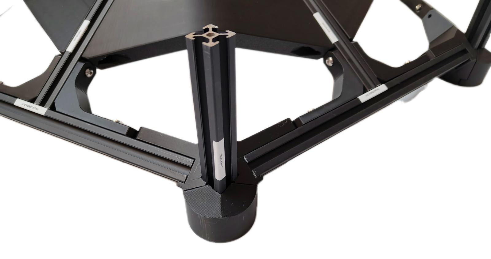
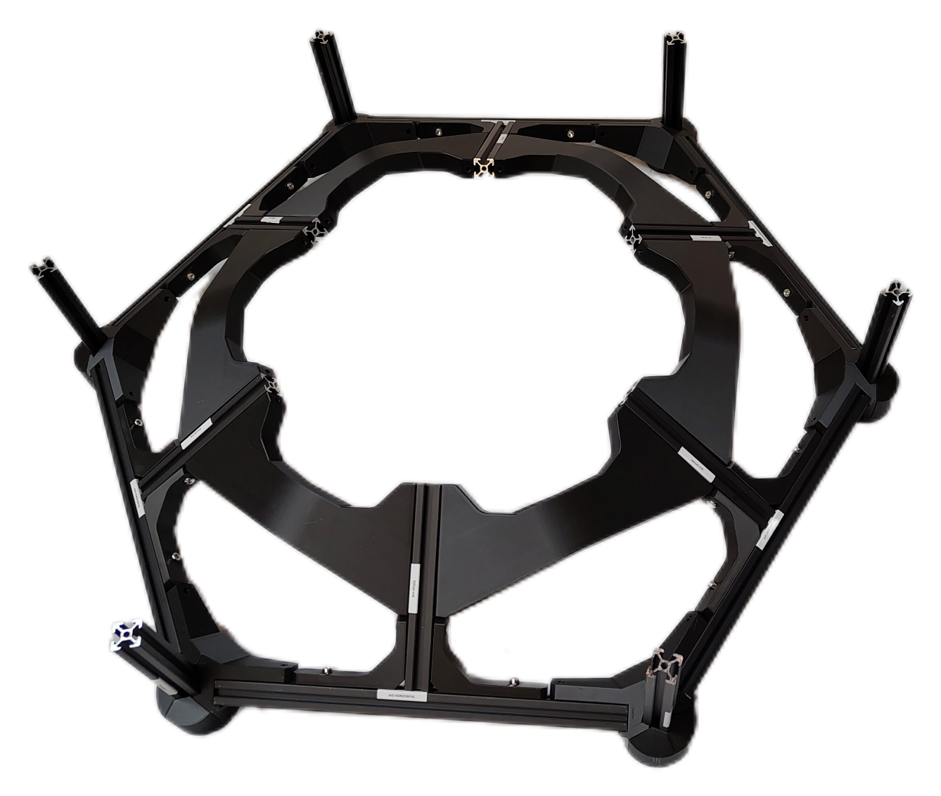
The External bracket — covers are already on, fitted in Build the hex frame, step 9. If a corner is missing one, put it on before you stand piece C in it, because it is difficult to slide on afterwards.
Slot a length of aluminum extrusion, piece C (Layer vertical support), 154 mm, between the External bracket — cover and the External bracket — side. Push it up as far as it goes, then use 2 M5 × 16 mm socket / button head screws tapped through the holes near the bottom of the External bracket — side to secure the extrusion.
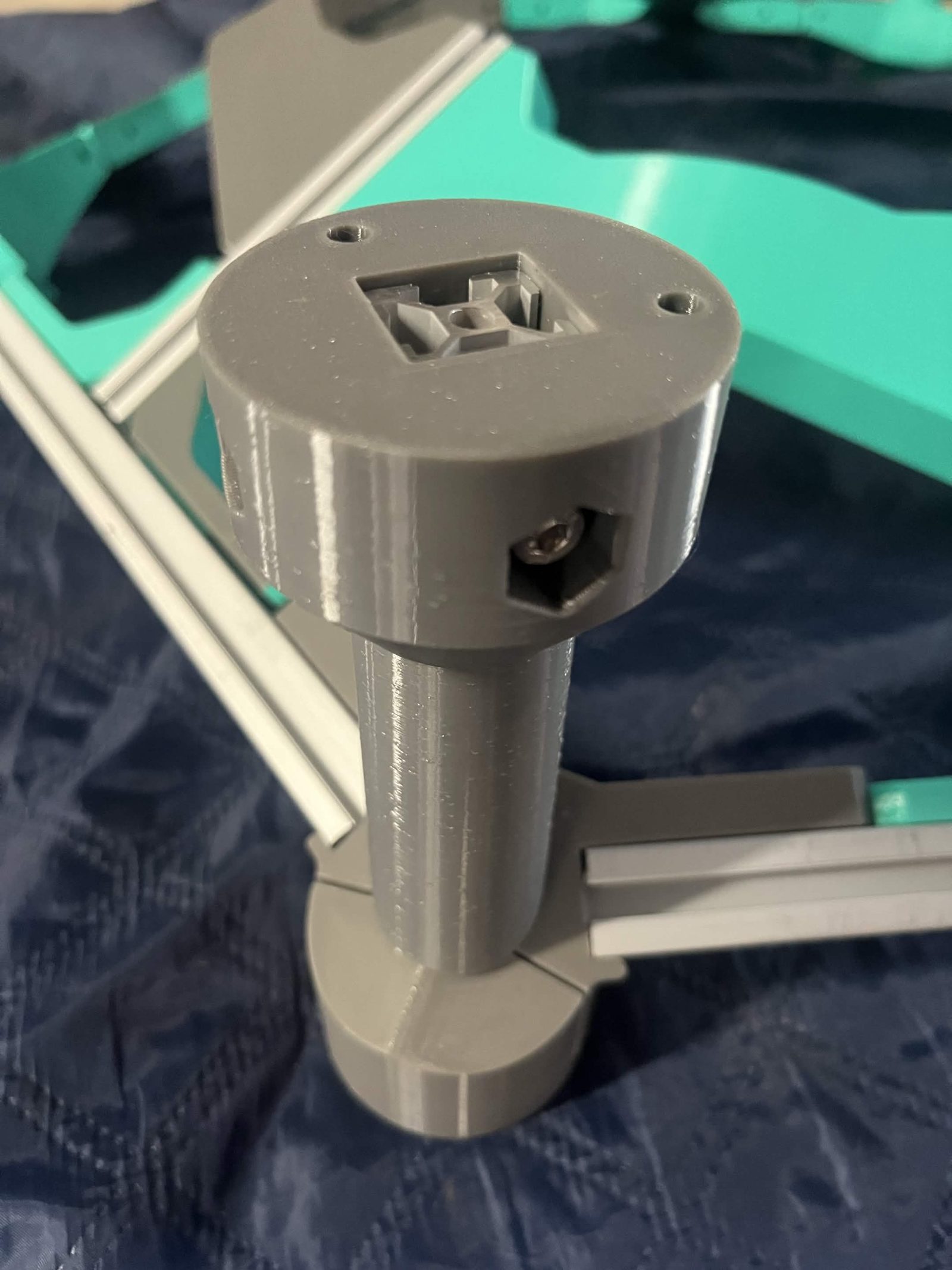
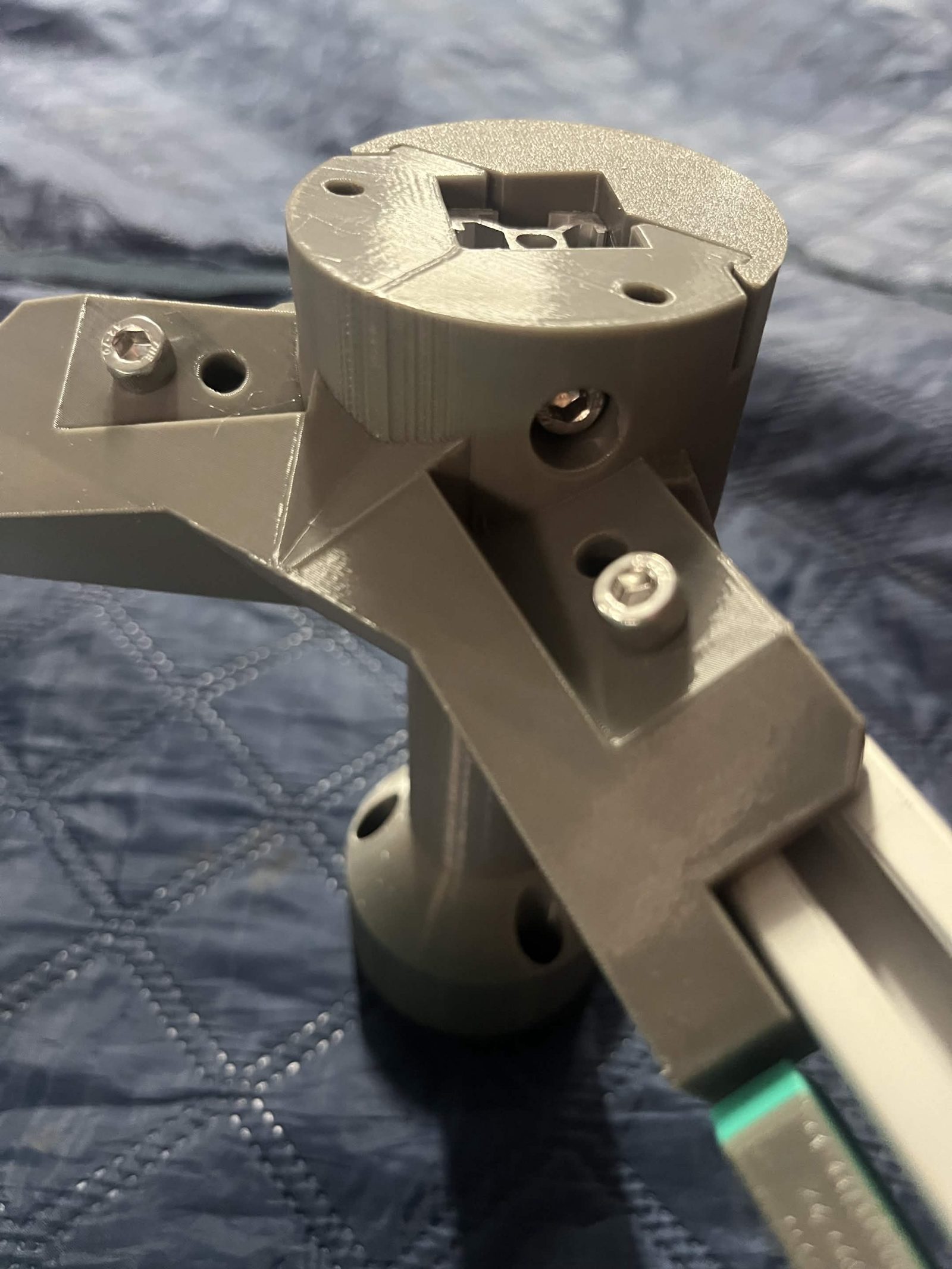
On each corner, slide an External bracket — bottom vertical onto piece C (Layer vertical support), ensuring the angles of the External bracket — bottom vertical align at the bottom. Secure them with 2 M5 × 16 mm socket / button head screws through the outer holes on the External bracket — bottom vertical. The end of piece C should now sit about 3 mm below the top of the External bracket — bottom vertical, as in the photos above.
If it comes up flush with the top of that bracket, or stands proud of it, check which piece you have. Several of the framing lengths are close together, and piece B is 158 mm against piece C's 154 mm. The framing cut list has every length.
Matching parts from the same print run are embossed with a shared set code (e.g. "b2") on both the External bracket — side and the External bracket — bottom vertical. Keep marked pairs together so brackets don't get mixed across corners.
The finished result
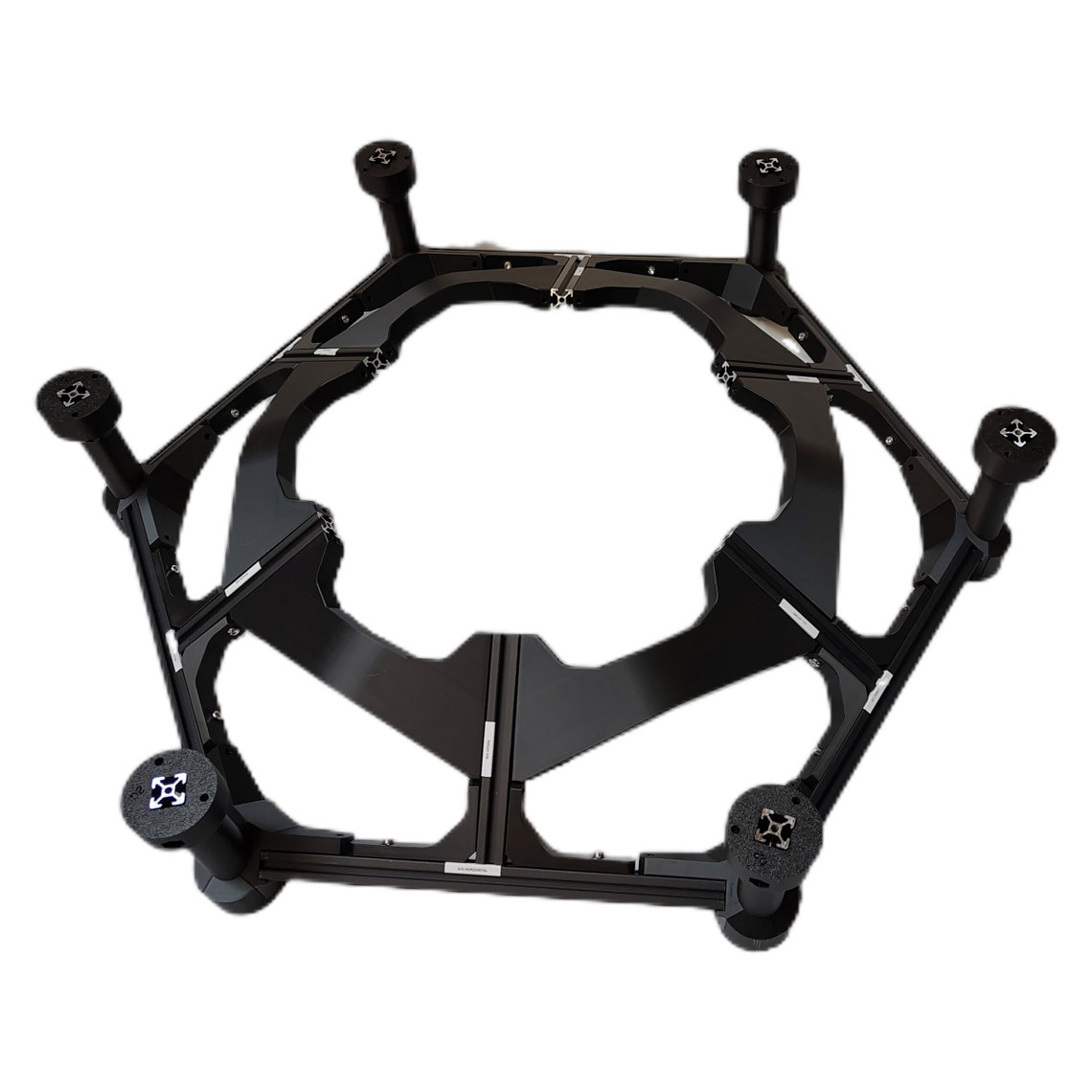
The hexagon closed, with a vertical standing in every corner under its External bracket — bottom vertical.
The Bin frame page contains the instructions for the entire stack, and is where you should return once you're done here.