
Chute — Chute core
Chute core
How-to guideThe chute assembly. Build one per layer.
Parts needed
Printed parts
- 1×
Heat inserts
- 18×
Tools needed
- Soldering iron or heat-set insert press
The chute is what steers a part into the right bin. Build one per layer, N for an N-layer machine. The bottom interface doesn't add any extra chutes of its own, it's a mounting stage the bottommost chute sits on, bridged to it by a layer connector.
The heat inserts are in the parts list above. The screws that hold the four sub-assemblies on are on their own pages, listed where they are driven.
Fastener icons match the parts list: the silhouette is the head shape, the colour is the thread size. M3 M4 M5 M6
One chute is the chute core plus four things that bolt onto it:
- Door module, one per chute: the door, the bearing assembly, the servo adapter and the servo in its bracket, built as a unit. See Door module.
- Layer adapter board, one per chute. See Layer adapter board.
- Funnel bracket (left) and Funnel bracket (right), one of each. See Funnel brackets.
- Layer connector A and Layer connector B, one of each. See Layer connectors.
Step 1 Preparation
Press the heat inserts into the chute core before you mount anything else onto it. See installing heat inserts for the technique.
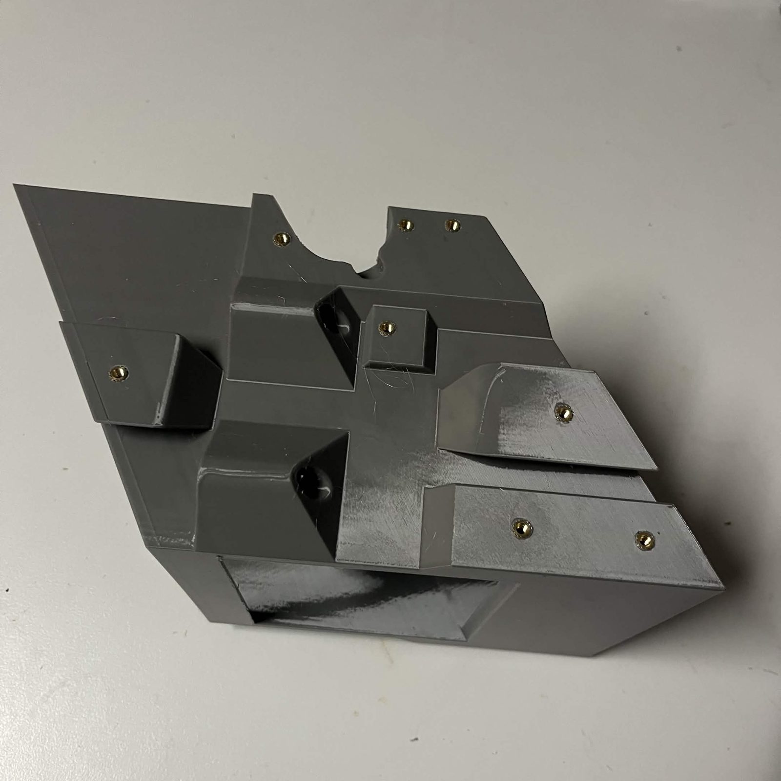
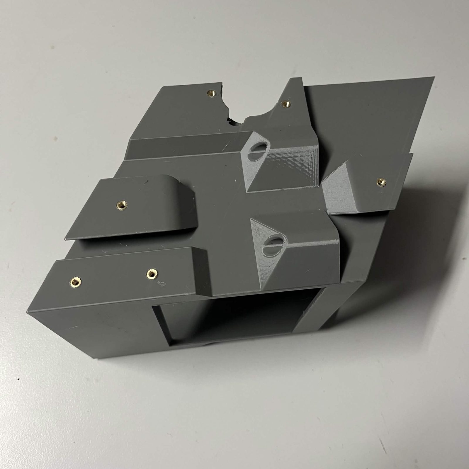
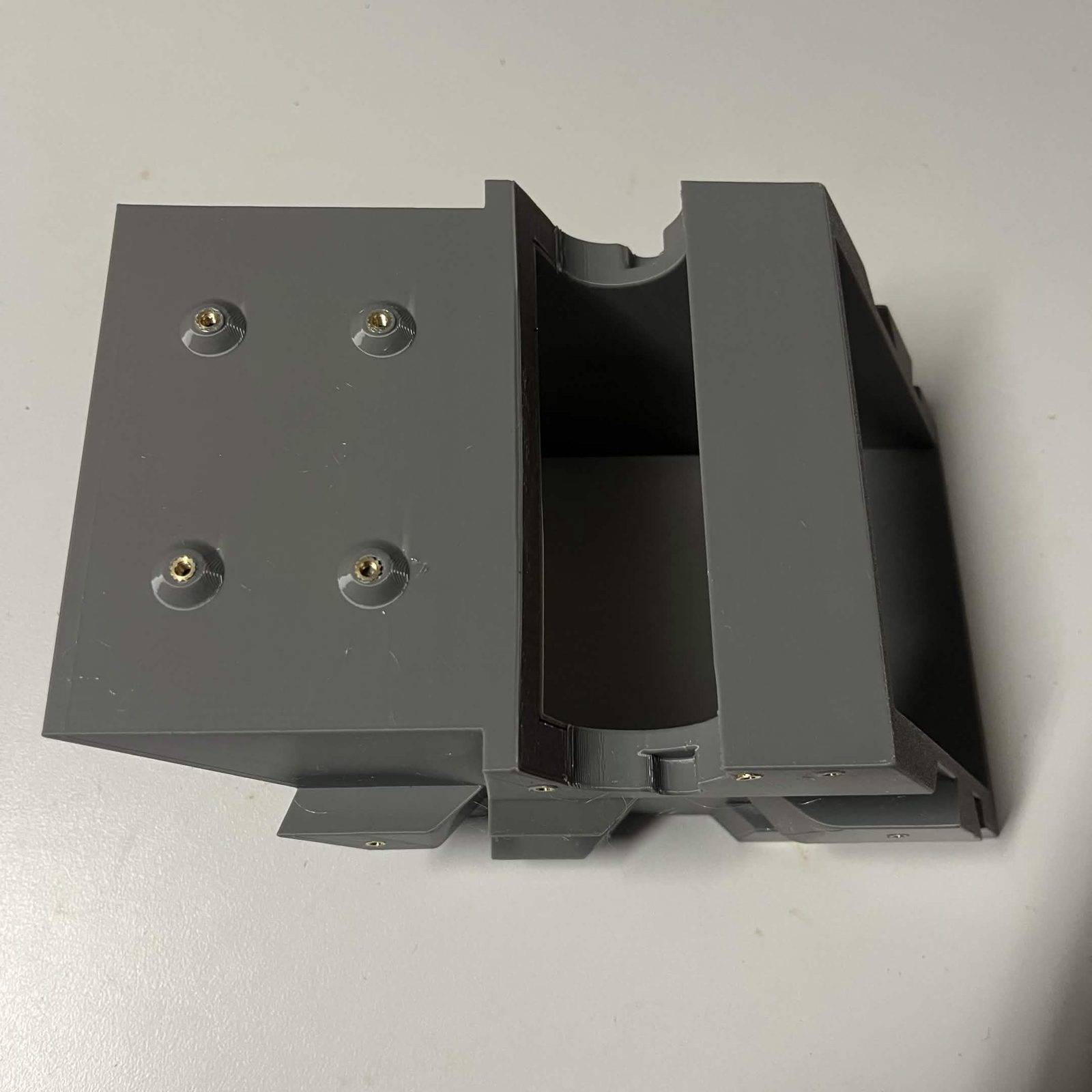
Chute core: 18 × M3, which is every insert on this page: 6 for the door module (4 for its two bearing covers, 2 for the servo bracket arms), 4 for the layer connectors, 4 for the layer adapter board, and 4 for the funnel brackets. This is separate from the bearing assembly's own 10 inserts, which live in the bearing race and holders themselves.
All 18 are the same insert, split 8 + 6 + 4 across three faces. The photos below show one face at a time, with the brass already in.
Step 2 Bolt the four sub-assemblies on
Fit them in this order, each on its own page, and each with its own screws in its own parts list:
- Door module, bolted on as a unit
- Layer adapter board
- Funnel brackets, left and right
- Layer connectors A and B
Every insert you pressed in at step 1 takes a screw from one of those four pages. That is why the inserts are listed here and the screws are not.
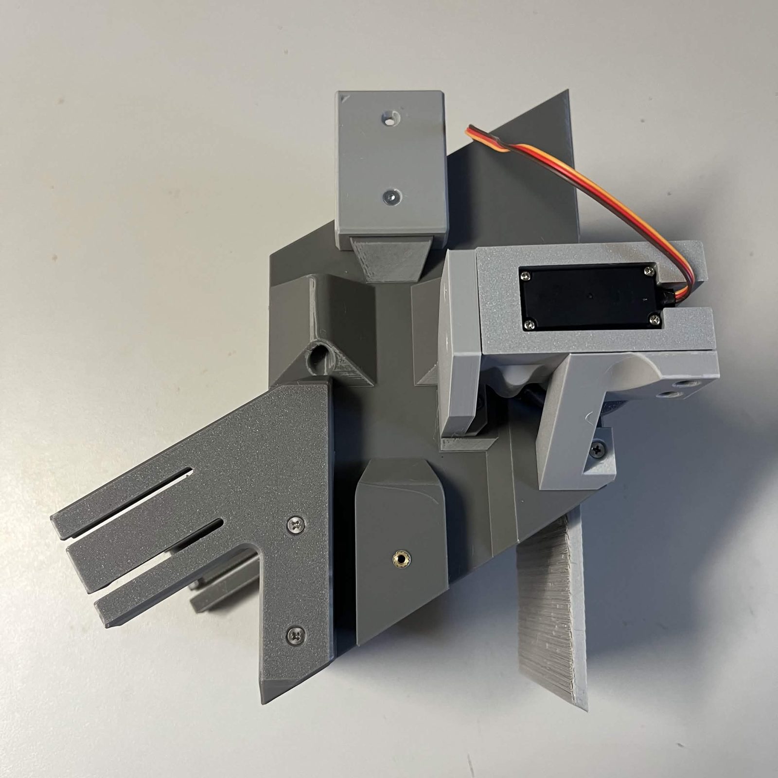
The finished result
The chute is complete when all four are on. Repeat for every layer.
The Chute page contains the instructions for the whole chute, and is where you should return once you're done here.