
Chute — Layer adapter board
Layer adapter board
How-to guideThe board that drives the servo.
Parts needed
Custom PCBs
- 1×
Electronics
- 1× 300mm
Screws
- 4× 6mm
A an interchangeable alternative works (hover for what).
Tools needed
- Hex key, 2 mm for a button head or 2.5 mm for a socket head
Each layer carries one basically Layer Adapter Board, the in-house board that breaks out the control board's ribbon connectors for that distribution layer and drives the layer's servo. One per layer.
The fasteners and quantities are in the parts list above and are called out inline at each step.
Fastener icons match the parts list: the silhouette is the head shape, the colour is the thread size. M3 M4 M5 M6
- The 4 M3 inserts the board sits on are part of the chute core's 18, not extra ones.
- The board is the only thing on the chute that uses a M3 × 6 mm socket / button head screw.
Step 1 Screw the board onto the chute core
Static caution: this is a bare board. Touch a grounded metal surface before handling it, and handle it by its edges, avoiding the connectors and components.
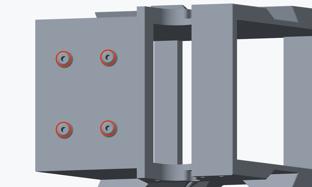
Seat it over the four inserts and fasten it with 4 M3 × 6 mm socket / button head screws. Do not overtighten.
Step 2 Connect the ribbon cables (`RIB1`, `RIB2`) and the servo
Do these now, while the chute is still on the bench. Once it is in the frame the three connectors are hard to reach.
The board has two identical 16-pin sockets. J3 is the ribbon coming in (RIB1 or RIB2) and J4 is the ribbon going on down to the next layer (RIB2). Nothing but the designator printed on the board tells them apart.
A board fed on J4 gets no signal at all, and every layer below it moves the wrong flap.
This layer's servo plugs into J5, the 3-pin header beside them: pin 1 signal, pin 2 servo power, pin 3 ground.
Put the 300 mm (12 in) ribbon (RIB2) from the parts list into J4 now and leave its far end loose. It only reaches the board below once the chutes are in the frame, so it is joined up there, at the same time as the layer connectors.
J3 takes the ribbon (RIB2) coming down from the board above. On the topmost chute that is the long ribbon from the control board (RIB1) instead, at connecting the components, step 5.
Full harness routing is covered in the harness drawings.
The finished result
The board screwed down on its four inserts, the servo in J5, and the 300 mm (12 in) ribbon (RIB2) in J4 with its far end loose. J3 is fed once the chute is in the frame.
The Chute core page carries the other three sub-assemblies that go on the same core, and is where you should return once you're done here.